
Anchor channel systems are cast into a concrete member. They are used to attach both structural and nonstructural components. Attachment of nonstructural components, such as curtain wall, is a typical anchor channel system application. Traditionally, anchor channel systems have been designed using manufacturer’s data and allowable stress design. Anchor channel systems can now receive recognition under the International Building Code (IBC) for design with strength design provisions. The International Code Council Evaluation Service (ICC-ES) has developed the Acceptance Criteria for Anchor Channels in Concrete Elements (AC232) to qualify anchor channel systems, and to design these systems using the provisions given in AC232 and in the anchoring-to-concrete provisions provided in the American Concrete Institute (ACI) publication Building Code Requirements for Structural Concrete (ACI 318).
History of Anchor Channel Design
Anchor channels have been in use for over 100 years. An anchor channel is part of an overall system consisting of the fixture being attached, T-bolts, a steel channel and anchor elements. T-bolts attach the fixture to the channel via the channel lips. The forces acting on the fixture are transferred through the channel into the concrete via the anchor elements. Figure 1 illustrates curtain wall attachment using an anchor channel system.
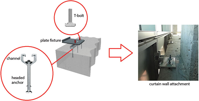
Figure 1. Anchor channel system.
AC232 was developed to qualify anchor channel systems for recognition under the IBC, and to utilize anchoring-to-concrete strength design provisions for anchor channel system design. AC232 test programs establish the structural performance of anchor channel systems to resist static loads, wind loads, and seismic loads. The design of anchor channel systems is not within the current scope of ACI 318. However, AC232 Section 3.0 Design Requirements provides amendments to the ACI 318 anchoring-to-concrete provisions that permit the design of anchor channel systems as if they were included in ACI 318 anchoring-to-concrete provisions.
Anchor channel systems satisfying the AC232 test programs may receive recognition under the IBC via an ICC-ES Evaluation Service Report (ESR). The ESR is based on the design provisions given in Section 3.0 of AC232.
Development of AC232
AC232 was first approved by the ICC-ES Evaluation Committee in October 2010. The original purpose of AC232 was to provide provisions for the qualification and design of anchor channel systems to resist tension loads and shear loads acting perpendicular to the longitudinal axis of the channel in normal weight concrete elements. Anchor channel systems satisfying these provisions can now receive recognition under the IBC via an ESR. The original AC232 provisions were based on European provisions for qualification and design with adoptions based on the anchoring-to-concrete provisions in ACI 318.
A task group was formed by the Concrete and Masonry Anchor Manufacturers Association (CAMA) to support further development of AC232. The task group, designated “Task Group AC232”, is comprised of manufacturers of anchor channel systems as well as representatives from academia, regulatory bodies, testing laboratories and professional and technical associations. The efforts of Task Group AC232 have resulted in several improvements and additions to the original AC232 provisions.
Design provisions for shear load acting in the direction of the longitudinal channel axis were not originally included into AC232 due to insufficient research defining qualification and design for this condition. Therefore, one of the initial efforts for Task Group AC232 was to propose and develop design provisions for the qualification and design of anchor channel systems when the applied shear load acts in the direction of the longitudinal channel axis.
Another significant effort of the task group was to develop provisions for the qualification and design of anchor channel systems in structures assigned to Seismic Design Category C, D, E or F. Anchor channel system design in structures assigned to Seismic Design Category A and B is considered a “non-seismic” design application in AC232. These extensions to AC232 were approved by the ICC-ES Evaluation Committee in February 2015.
Next, Task Group AC232 proposed additional design provisions for the transfer of shear load acting in the direction of the longitudinal channel axis. These provisions, which include testing and evaluation for locking channel bolts in combination with non-serrated channels, and for serrated channels in combination with matching serrated channel bolts, were subsequently added to AC232 in June 2015.
Finally, in October 2015, the ICC-ES Evaluation Committee approved Task Group AC232 modifications permitting the use of anchor channel systems in all-lightweight and sand-lightweight concrete. All of these changes result in AC232 now providing a complete framework for anchor channel system recognition under the IBC.
Design using AC232
Loads acting on a fixture must be transferred through the anchor channel into the concrete via the T-bolts and the anchor elements. T-bolt loads result from the applied loads acting on the fixture. Loads acting on the T-bolts are transferred through the anchor channel into the anchor elements.
AC232 permits calculation of the load distribution on anchor elements using either an elastic analysis, that takes into account the elastic support by anchors and the partial restraint of the channel ends by concrete compression stresses, or using a triangular load analysis. Use of the triangular load analysis to determine the loads acting on each anchor element is described in this article.
Before the loads acting on each anchor element can be determined, the loads acting on the T-bolts must be determined. Assuming the fixture is rigid, a linear elastic stress/strain analysis can be used to calculate the tension and shear loads acting on each T-bolt.
Next, the load acting on each anchor element resulting from the load acting on each T-bolt must be calculated. If a triangular load analysis is used, each T-bolt load can be assumed to have an influence on each of the anchor elements within a given distance from the T-bolt. The magnitude of a T-bolt load on an anchor element will be proportionate to the distance of the anchor element from that T-bolt. If the anchor channel system consists of more than one T-bolt, a linear superimposition of each T-bolt load on each anchor element must be made to determine the total load on each anchor element. Anchor channel system strength design calculations are based on the most unfavorably loaded anchor element, and the concrete geometry associated with this element. Figure 2 illustrates how the triangular load distribution is used to determine the loads acting on each anchor element for a tension loaded anchor channel.
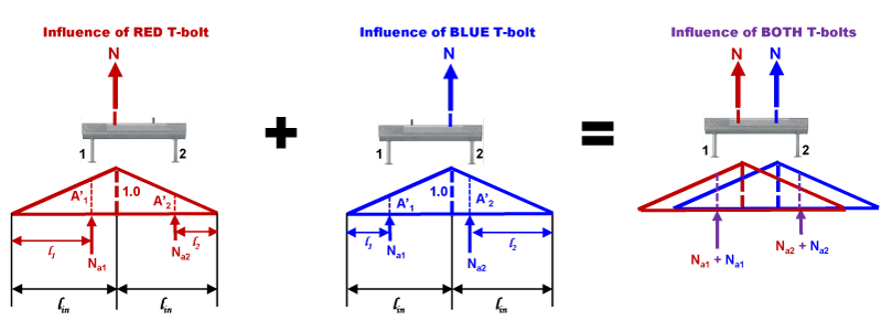
Figure 2. Anchor channel system triangular load distribution.
Strength design requires a calculated nominal tension strength (Nn) or nominal shear strength (Vn) to be multiplied by a strength reduction factor (φ-factor) to obtain a design strength (φNn or φVn). Design strengths correspond to possible failure modes. The design strength must be greater than or equal to the corresponding factored tension load (Nua) or factored shear load (Vua). Anchor channel system design strengths must be calculated for each anchor element and checked against the factored load acting on that element. φ-factors corresponding to steel and concrete failure modes for a particular anchor channel system are reported in the ESR. Figure 3 illustrates possible failure modes for anchor channel systems.
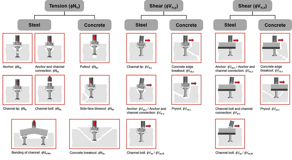
Figure 3. Anchor channel system failure modes.
AC232 permits the use of anchor reinforcement to preclude concrete breakout failure in tension or shear. Bars designed as anchor reinforcement must be developed on both sides of the potential concrete breakout surface. AC232 also permits the use of supplementary reinforcement to provide additional concrete breakout capacity in tension or shear. Concrete breakout failure is not precluded when supplementary reinforcement is used because supplementary reinforcement is not specifically designed for development on both sides of the potential concrete breakout surface.
Anchor channel system design in structures assigned to Seismic Design Category A and B is considered a static design application in AC232. Design strengths for static tension correspond to tension steel and concrete failure modes. Design strengths for static shear correspond to shear steel failure modes and to concrete failure modes based on whether the shear load acts perpendicular to the channel axis or in the longitudinal direction of the channel axis. Static steel nominal strengths for a particular anchor channel system are reported in the ESR. Nominal concrete strengths for static tension and static shear must be calculated using the static provisions defined in AC232 Section 3.0, and also reported in the anchor channel system ESR.
Anchor channel system design in structures assigned to Seismic Design Category C, D, E and F is considered a seismic design application in AC232. Design strengths for seismic tension correspond to tension steel and concrete failure modes. Design strengths for seismic shear correspond to shear steel failure and to concrete failure based on shear load acting either perpendicular to the channel axis or in the longitudinal direction of the channel axis. Nominal steel strengths for seismic tension and seismic shear will be reported in the ESR. Nominal concrete strengths for seismic tension and seismic shear must be calculated using the seismic provisions defined in AC232 Section 3.0, and also reported in the anchor channel system ESR.
Shear load acting on the anchor channel system must be considered regarding whether it acts perpendicular to the longitudinal channel axis or in the direction of the longitudinal channel axis. Load acting perpendicular to the channel axis is primarily transferred into the concrete via the side of the channel. Only a small portion of the load is transferred into the concrete via the anchor elements; however, AC232 provisions conservatively assume only the anchor elements are effective in transferring shear load into the concrete. When the shear load acts perpendicular to the longitudinal channel axis, concrete breakout and concrete pryout are calculated using AC232 provisions, which are also reported in the anchor channel system ESR.
When the applied shear load acts in the direction of the longitudinal channel axis, only the anchor elements are assumed to be effective in transferring this load into the concrete. ACI 318 anchoring-to-concrete provisions are used to calculate concrete breakout for this condition. Pryout is calculated using AC232 provisions, which are also reported in the anchor channel system ESR. Refer to a particular anchor channel system ESR for additional information. Figure 4 illustrates the assumed load transfer for anchor channel systems.
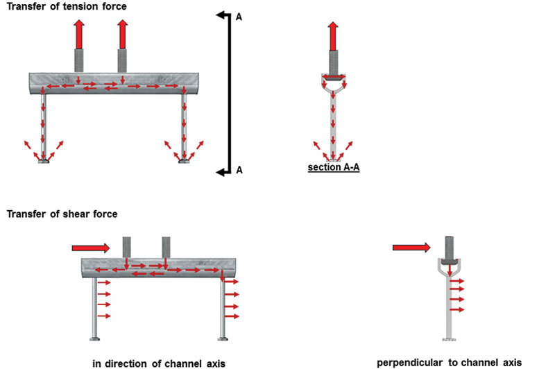
Figure 4. Anchor channel system load transfer.
If the calculated design strengths for each failure mode being considered are greater than or equal to the corresponding factored load for that failure mode, the anchor channel system design is satisfied pending a combined load interaction check. If tension and shear loads act on the anchor channel system, the combined tension and shear interaction for each failure mode must be satisfied. Reference AC232 Part D.7.4, Section 17.6.4 (ACI 318-14) for specific interaction equations, which can be summarized as follows:
- tension and shear interaction for steel failure of the T-bolt
- tension and shear interaction for steel failure of the connection between the anchor element and the channel
- tension and shear interaction for steel failure due to point of load application on the channel lip (channel lip failure or flexural failure of the channel)
- tension and shear interaction for concrete failure (pullout, concrete breakout or side-face blowout in tension, and concrete breakout or pryout in shear)
Future Provisions for AC232
Although the anchor elements of an anchor channel system can be considered cast-in headed studs, AC232 design provisions to calculate nominal concrete breakout strength in shear lead to more conservative results compared to results obtained using ACI 318 anchoring-to-concrete provisions for cast-in headed studs. There are several reasons why AC232 design provisions deviate from the provisions given in ACI 318:
- Research on anchor channels located close to a fixed edge and loaded in shear is limited; therefore, AC232 provisions to calculate concrete breakout strength in shear are based on simplifications
- Shear load acting perpendicular to the longitudinal channel axis is primarily transferred into the concrete via compression stresses between the side of the channel and the concrete. Only a small portion of this load is transferred into the concrete via the anchor elements. However, for reasons of simplicity, AC232 assumes shear load is acting perpendicular to the longitudinal channel axis is transferred into the concrete exclusively by the anchor elements.
- The AC232 triangular load distribution method results in higher loads on the anchor elements compared to ACI 318, which assumes a uniform load distribution
- AC232 and ACI 318 use different models to calculate the effectiveness of anchor reinforcement in the concrete
Since anchor channel systems are a type of cast-in-place anchor, AC232 improvements are needed to permit a design that more effectively utilizes ACI 318 anchoring-to-concrete provisions. CAMA Task Group AC232 is working to develop AC232 provisions that better represent the load-bearing behavior of anchor channel systems. The long-term plan is to include anchor channel systems within the scope of ACI 318 anchoring-to-concrete provisions.
AC232 currently limits anchor channel configurations to those produced from steel, with at least two anchor elements attached to the back of the channel profile. Anchor channels made of other materials, such as aluminum, is a future possibility. Only anchor channel configurations with I-shaped anchors or round-headed anchors are within the current scope of AC232. Anchor channel configurations that include reinforcing bars are often used for face-of- slab and corner applications; however, provisions for testing and design of these configurations are not included in the current scope of AC232. Additional research is required before these configurations can be included within the scope of AC232.
The current scope of AC232 limits anchor channel system embedment depths to a minimum value that precludes installation in very thin concrete members (e.g. concrete over metal deck). Additional research is needed to understand the load-bearing behavior of anchor channel systems for this application, thereby permitting design and installation at shallower embedment depths.
Summary
The International Code Council Evaluation Service (ICC-ES) Acceptance Criteria for Anchor Channels in Concrete Elements (AC232) establishes requirements for anchor channel systems to be recognized under the International Building Code (IBC). AC232 permits qualification and design of anchor channel systems in normal weight and lightweight concrete to resist static loads, wind loads, and seismic loads. AC232 design provisions are considered amendments to ACI 318 anchoring-to-concrete provisions. Recognition of anchor channel system compliance is provided by an ICC-ES Evaluation Report (ESR).▪