
What do you do when a client approaches you with an entirely unique structural challenge? That was the structural engineering dilemma presented to Uzun + Case by artist Tristan Al Haddad of Formations Studio who proposed a 35-foot tall, 65,000-pound thin shell concrete sculpture for the Promenade office tower in Atlanta.
The first engineering question was “Why concrete – there are many synthetic materials well suited to the creation of amorphous forms?” To which the artist responded, “I want to do something with concrete that has never been done before, to create something that is simultaneously delicate and solid, something that shows the hand of its creator.”
And so the journey began.
Fortunately, this seemingly free-form structure had been conceived utilizing computer-generated geometry and principles of structural behavior. In fact, Stealth is an assemblage of hyperbolic paraboloid shell elements. The use of hyperbolic paraboloid thin shell concrete forms was popularized by engineers such as Felix Candela and Heinz Isler in the 1950s and 1960s. The shells for Stealth are not uniform in thickness but curve in cross-section, leaving thinner edges and a thicker midsection. This creates the illusion of a thin profile throughout.
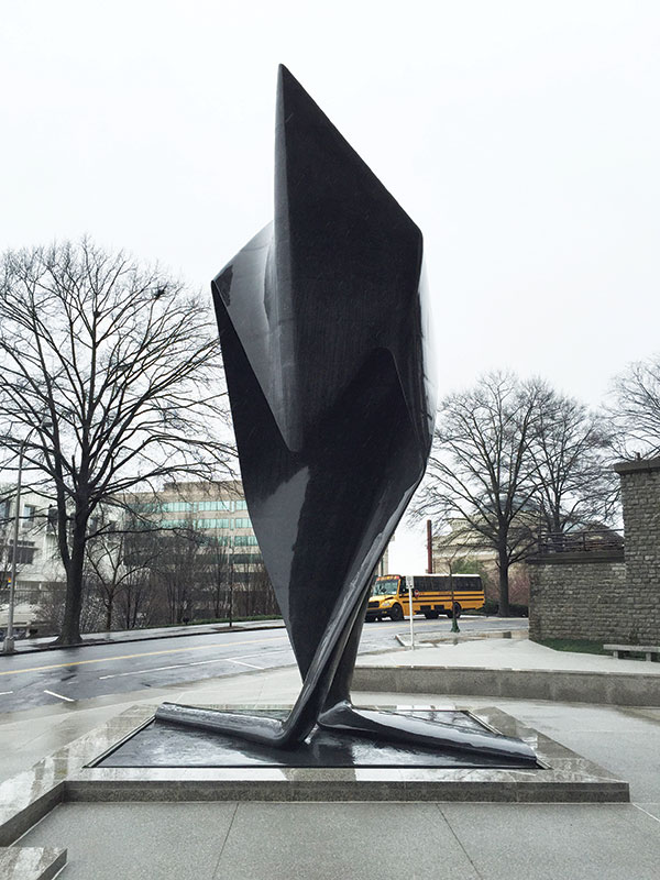
Stealth.
Structural Analysis
Work began by analyzing the structure with the finite element program SAP, using a mesh generated by Formations Studio and rectilinear shell elements of varying thicknesses to simulate the sculpture’s elliptical cross section. A centerline mesh was exported from the parametric modeling program Rhino and imported into SAP using the DXF format. The mesh was created by the artist using parameters specified by Uzun + Case. The varying thickness of the cross section was approximated by zones of constant thickness which stepped at their intersections with one another. The sharing of electronic information greatly expedited the analysis process.
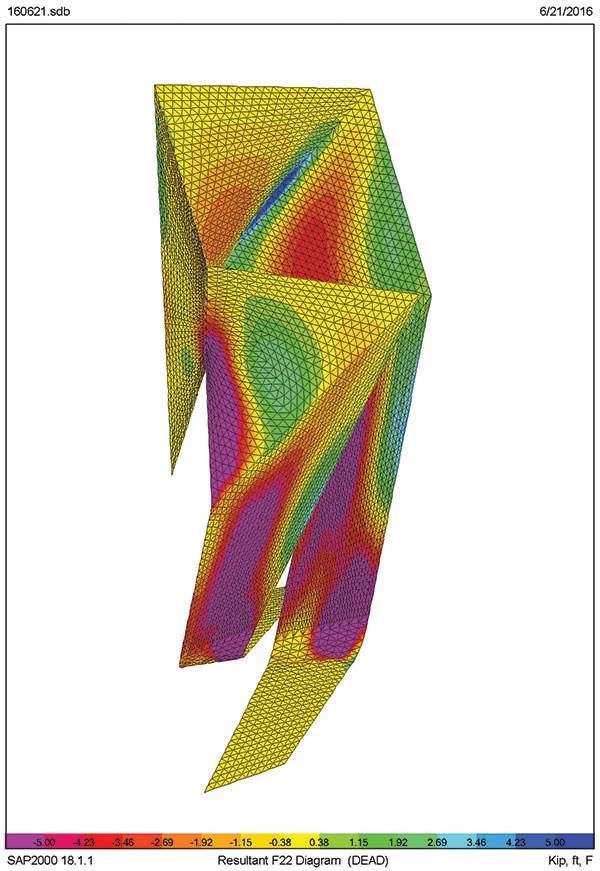
Stress diagram.
Both service and ultimate stresses/forces were considered. The service level results were based upon a 10-year return period and used to calculate crack widths and deflections. The ultimate level forces were based upon a 700-year return period and used for strength design. ASCE 7-10 ultimate wind speeds correspond to approximately a 7% probability of exceedance in 50 years (Annual Exceedance Probability = 0.00143; MRI = 700 years). A combination of wind and gravity forces controlled the design of the structure. Seismic forces were not critical. Reinforcement for crack control was calculated first, followed by an ultimate strength check.
The analysis results indicated that the upper portion of the sculpture behaved like a shell with relatively low stresses, necessitating a maximum thickness of only 7 inches. It was reinforced with a mat of #5 reinforcing bars at 4-inch on center each way.
The lower portion of the sculpture was controlled by bending, necessitating an increase in thickness to 14 inches. The high bending stresses are resisted by (2) #7 reinforcing bars at 4-inch on center vertically with #5 horizontal ties at 4-inch on center. The accurate bending of the vertical bars to fit within the exacting forms was a major challenge, which was executed in house by Formations Studio. The use of double #7s instead of #9 bars was based upon the studio’s limited bar bending capabilities.
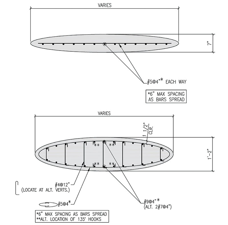
Upper portion cross section top. Lower portion cross section bottom.
Base supports consisted of four pinned nodes at each of the two legs. The position of the supports corresponded to the centroid of vertical reinforcing bar groups which connected the legs to the mat foundation below. The mat foundation is 12 feet x 15 feet x 16 inches thick, reinforced with #7@12 bottom and #6@12 top. The SAFE computer program was used to analyze and design this element based upon an allowable soil bearing pressure of 2000 PSF.
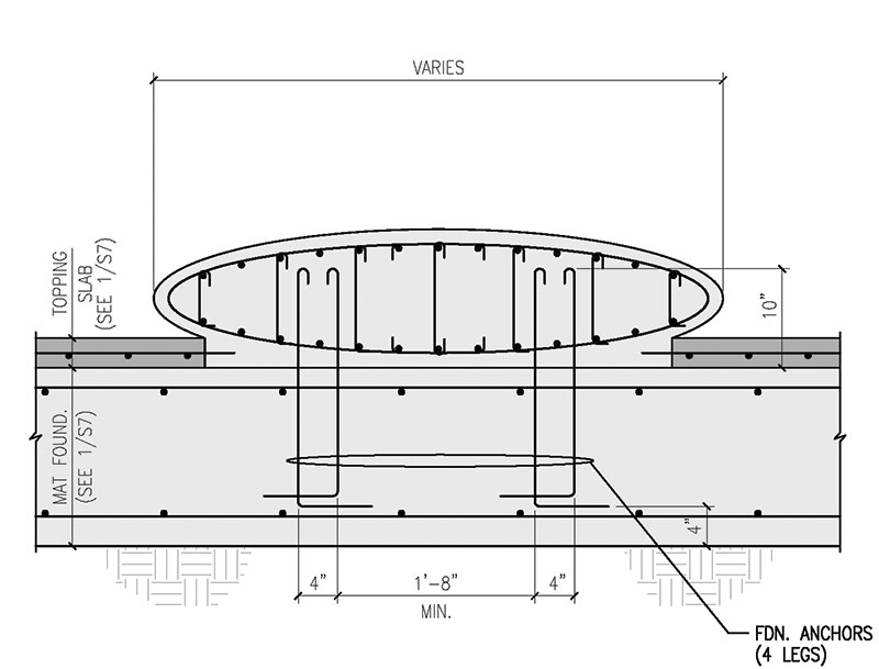
Leg to mat foundation connection detail.
Crack control and durability were primary design parameters. The structure was designed not to crack, except at the base where crack widths were limited to avoid durability concerns. Five (5) pounds per cubic yard of Forta Ferro fibers were added to control cracking and improve durability at thin cross sections. Cracking was evaluated using the computer program Response 2000 based on the reinforcement and combined bending, axial, and shear forces at each section. Crack widths were limited to 0.2 mm in general but to avoid excessive thickness at the base of the sculpture crack widths of 0.33 mm were allowed.
Formwork and Reinforcement Fabrication
Due to the complex and exacting nature of the structure, formwork and reinforcing steel fabrication was performed in the artist’s studio.
Several options were considered for the design of the formwork system, including a solid system of ¾-inch plywood layers. Ultimately, to minimize material usage, a two-way structural rib system was chosen. It consisted of ¾-inch plywood ribs skinned with three layers of ¼-inch marine grade plywood, providing the flexibility to form the synclastic and anticlastic double curvatures required by the sculpture.The digital modeling, indexing, and CNC routing of the formwork was a monumental effort given that each of the 183 pieces of formwork for the sculpture was unique.
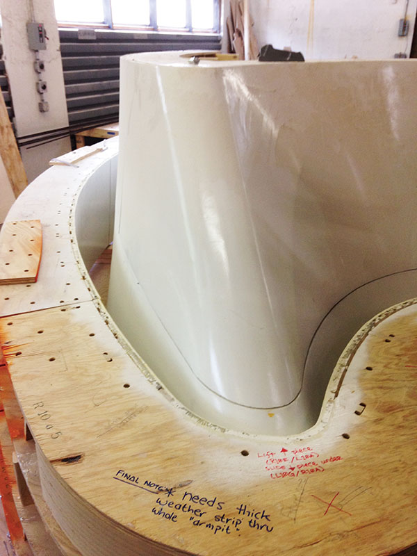
Formwork.
The rebar at the base was treated similarly with CNC cut templates made for each bar to enable accurate bending. The bars and formwork for each section were transported to the site as a complete assembly.
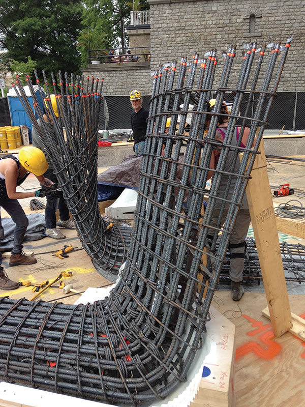
Base reinforcing.
Concrete Mixture
Initial studies for the structure considered steel fiber reinforced ultra-high performance concrete. This proved impractical due to the high flexural stresses at the sculpture base and the need to create continuity at construction joints. A 5000 PSI conventionally reinforced concrete design was selected.
The final mixture was developed with the assistance of Thomas Concrete Technical Services Laboratory. The mix design required 5000 psi and very high flowability to achieve the very thin profile details at the edge of the structure. Liquid integral color dosages were provided by Increte. Since aggregates make up such a significant portion of the mixture, and therefore greatly affected color, numerous lab batches were produced to look at local granite aggregates, imported black granites, and slags and finally the chosen material, a blue/black Georgia limestone. Seventy-six (76) ounce per cubic yard of SIKA ViscoCrete 2100 high range water reducer was used for dispersion, strength, and rheological properties.
Construction
To facilitate construction, an intricate scaffolding system was designed and built around the Sculpture, and erected in lifts as the formwork for the sculpture was placed. Form delivery was sequenced to avoid damage due to prolonged weather exposure. Formwork for the entire sculpture was left in place until concrete placement was complete.
The levelness, elevation, and orientation of the foundation of the sculpture were critical. The foot and ankle placement was one of the most challenging due to the unusual geometry and the large amount of reinforcement. The structure was built in four-foot lifts, with forms that were bolted together. Due to the computer controlled manufacturing process, the formwork fit-up was excellent.
The foot and ankle rebar was fabricated at the Formations Studio facility. All other reinforcement for the sculpture was bent on site. Much effort was made to ensure that the specified 1½-inch rebar clearances were maintained. Uzun + Case inspected all rebar before concrete placement.
All concrete was placed via a line pump system. Concrete arrived with an integral color, but a second color, ‘Carbon’, was added at the job site. Concrete spread averaged 24 inches. All concrete was vibrated for proper consolidation using a small head and motor assembly. Form removal was tedious due to the curvature of the sculpture.
Finally, Formations Studio painstakingly shaped and polished the surface to achieve the glass-like finish. The sculpture was shaped with a steel cup wheel and wet polished using a diamond pad system utilizing increasing fineness from 50 grit to 3000 grit. Finally, the structure was coated with a lithium polysilicate penetrating densifier/sealer (Pentra-Sil by Convergent Concrete Technologies).
Structural Monitoring and Performance
To verify structural modeling assumptions, Uzun + Case instrumented the finished sculpture with accelerometers to measure its fundamental frequency. The measured value of 2.5 hz was within 5% of the value predicted by the eigenvalue analysis when adjusted for average actual vs. specified concrete strengths. This gave added confidence that the complex computer model had accurately captured the behavior of the structure.
The finished surface was inspected and observed to be of excellent quality and free of visible cracks other than those at the ankle zones, which are of predicted width. It was satisfying to have predicted the cracking performance accurately, but the author was secretly hoping for the cracks not to appear! This demonstrates the importance of managing expectations in advance since all parties were satisfied with the resulting performance.
Collaboration
Artist and engineer, working together, were able to create a concrete structure of extraordinary geometric complexity, thinness, and grace. Stealth was the result of a collaborative and respectful working relationship between artist and engineer. The artist thought like an engineer in conceiving of a form that was not only interesting and beautiful but also structurally feasible and buildable. The engineer thought like an artist in striving to make the structure not only stable but also as thin and as faithful to the artist’s vision as possible.▪