
DeSimone Consulting Engineers was an Outstanding Award Winner for the Grove at Grand Bay project in the 2015 NCSEA Annual Excellence in Structural Engineering Awards program (Category – New Buildings over $100M).
Designed by Bjarke Ingels Group (BIG), Grove at Grand Bay, the first truly twisting buildings in the United States, will be an iconic residential project located at the former site of the Grand Bay Hotel in Miami.
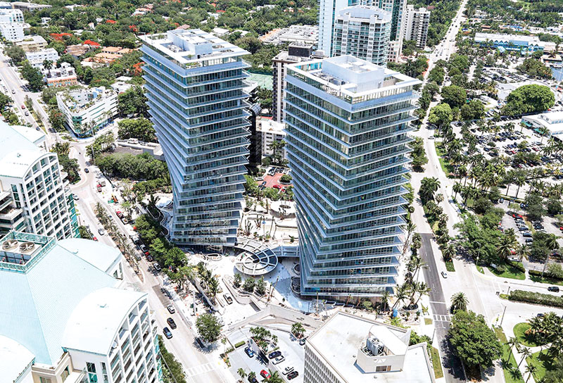
Grove at Grand Bay features two towers rising 20 stories above a lush landscaped two-story podium. The two towers are low density, with 98 spacious custom homes featuring 12-foot high ceilings and 14-foot deep balconies. To capture the full panoramic views of Biscayne Bay and the Miami skyline, the architect rotated the towers incrementally along the height for a total rotation of 38 degrees.
Site constraints required a square footprint for the base of the south tower. The floor plate increases in length as the building twists, maximizing the sellable area. The north tower footprint remains a constant rectangle throughout its height. When completed, these towers will be the first LEED Gold Certified residential buildings in Miami-Dade County.
Horizontal Shear Force
The true twisting nature of the columns posed a number of structural challenges that demanded a fresh, innovative approach. The foremost challenge was to resist torsion generated in the tower core due to the sloping column geometry. The horizontal component of the gravity load in the columns is resolved in the slabs by transferring it to the interior core shear walls, which are the only consistently vertical structural elements in the building.
Since all the columns are rotating in the same direction, additional horizontal thrust from all columns creates a large shear force in the tower cores. The magnitude of shear forces in the tower cores due to self-weight was considerably higher than that generated by the design hurricane wind loads. To minimize the total horizontal shear force transfer into the core walls, a “hat truss” was introduced at the roof. The hat truss is comprised of a series of beams cantilevered from the cores and connected to all the columns. The hat truss collects superimposed dead load and live load, delivering the “suspended” loads directly to the core as a vertical load component. This alternate load path reduced torsional forces in the core by approximately 30 percent.
The magnitude of the combined horizontal shear force from the building self-weight and the hurricane wind loads would require conventionally reinforced concrete shear walls to be 6 feet thick. To regain valuable real estate, a composite concrete shear wall and link beam system was introduced. The composite action between steel and concrete allowed a substantial wall reduction to 30 inches thick. Internal steel plates with thicknesses of up to 3.75 inches were required to achieve the overall wall thickness. Rolled steel sections replaced traditional reinforcing steel in the boundary element zones. The plates extend vertically for 15 floors, with normal reinforcing steel continuing to the roof.
Building Movement
Building movement was another challenge, especially before the “hat truss” was installed and loaded. A linear analysis was performed, and it was determined that there was considerable horizontal displacement of the floors due to self-weight alone. Therefore, an extensive analysis was conducted to estimate the accurate building movement using a nonlinear construction sequence analysis. The tower floor plates are cambered rotationally, as much as a half-inch relative to the floor below, for 75% movement due to the building self-weight to compensate for the displacement. This allows the tower to settle back to the design coordinates just before the hat truss reaches design strength.
Flexible Unit Layouts
Column-free interiors were provided to allow for maximum flexibility of the unit layouts. Resulting spans between the core and perimeter columns ranged up to 40 feet and balconies cantilevered up to 16 feet. DeSimone proposed a scheme with an 8-foot wide, 16-inch thickened slab around the core to allow a 10-inch thick post-tensioned slab to span the remaining distance. This provided a 12-foot clear ceiling dimension.
Design Flood Elevation
As is common in many coastal areas of Florida, this site is subject to flooding during tropical storm events. Portions of this site are located in a FEMA designated AE-12 flood zone. For insurance requirements, this prescribed the entire basement slab to be designed to a design flood elevation of +13.0 NGVD, resulting in a design uplift pressure of 710 pounds per square foot. Multiple-pile podium caps were replaced with a single larger pile with a cap poured monolithically with the basement slab to reduce the cost of excavation and dewatering. Additional cost savings were realized by using post-tensioning to reduce the mild steel in the slab.
Cost Conclusions
The South Florida residential market is currently leading the construction boom in the United States. In such a competitive environment, cookie-cutter architecture is unlikely to sell at desirable prices and developers are demanding more technically challenging and unique designs. However, there is a limit to what the market will pay and how much a developer is willing to spend. With the structural ingenuity used in the Grove at Grand Bay, the premium for a twisting architectural design was limited to an additional 18 percent above traditional construction. Without extraordinary interdisciplinary work between the entire design team, the project would not be a success.▪