
Saint Venant established his theory of torsion (1853) by assuming axially invariant modes of tangential and axial (warping) displacements. In conjunction with known static boundary conditions, the equations of elasticity were satisfied leading to an exact solution for pure torsion. His theory assumes free warping displacement and, when this is restrained, the torsional stiffness is increased depending on the cross-sectional shape. The basic beam finite element formulation assumes free warping, but there are also elements that include a warping freedom thereby allowing warping to be controlled.
This article details a design scenario where the manufacturing of an I-shaped structural steel member was changed from rolled to machined. This change enabled thick, integral end plates to be machined to allow bolting to adjacent members. Before the design change, warping restraint had not been considered. With the addition of integral end plates, it became apparent a study would be required to establish how warping restraint changed the (torsional) stiffness of the member. Beam elements were used to model the structural members and the influence of different element formulations on the structural response were compared. Also, verified three-dimensional solid models were used to provide validation for the beam solutions. To verify the modeling approach adopted, and to provide solutions that may be checked with closed-form solutions, members with other cross sections were also considered.
In preparing this article, benchmark studies on warping restraint were not found, even in the documentation of ANSYS (the FE software used for this study). It is hoped, therefore, that this article might be useful to fellow structural analysts when considering how to model beams with warping restraint.
The three cross sections and other geometric and material properties considered are shown in Figure 1.
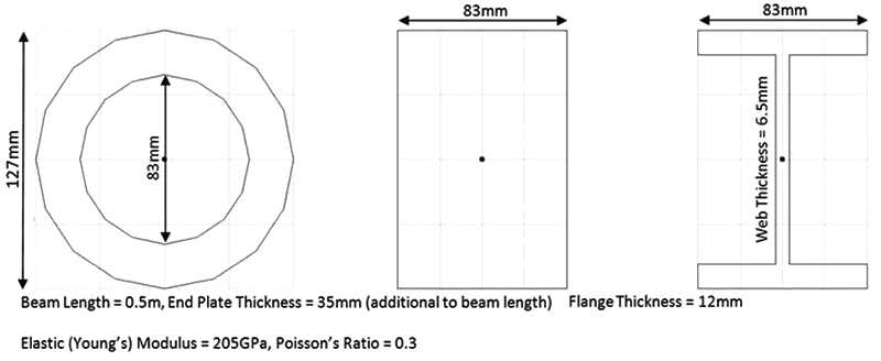
Figure 1. Cross-sectional and other geometric and material properties.
Closed-Form Solutions
The theory of pure torsion defines the torsional stiffness of a beam of length, L, as the torque, T, divided by the relative rotation, θ, of the two ends of the beam measured in radians:
[pmath]T/theta = GJ/L[/pmath]
Where G is the shear modulus and J is the polar second moment of area of the cross section. The torsional stiffnesses, T/θ, for the three beams defined above are 3293 kNm/rad, 2269 kNm/rad and 16.6 kNm/rad, respectively, for the circular, rectangular and I-shaped beams.
Boundary Conditions
For pure torsion, the end sections of the member are assumed to rotate such that the circumferential displacement is proportional to the distance from the axis of rotation. Longitudinal distortions of the cross-section at the element ends depend on the warping restraint which may vary between the free and restrained conditions:
1) Free Condition – nodes on the end sections are free to move independently in the axial direction.
2) Restrained Condition – nodes on the end section remain in the same plane which is free to translate axially (although as a result of symmetry this translation will be zero).
To implement these kinematic conditions, one first needs to recognize that nodes of solid elements possess only translational degrees-of-freedom.
As such, one simple method to compute rotation where torque may be applied or rotation constrained at the ends of a solid model is to add a beam element. This element should be collinear with the centroidal axis of the solid model, with one node positioned at the centroid of each end section of the solid model. The axial rotation of this node may then be coupled, appropriately, to the in-plane translations of the nodes on the end section of the solid model to give a pure rotation of the end section.
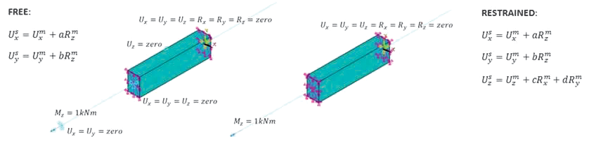
Figure 2. Boundary conditions. The coefficients a and b are determined from the relative positions of the master and slave node. Translations, U, and Rotations, R, have subscripts indicating the asix and superscripts, where required, representing slave or master nodes.
The nodes at the ends of the beam lying in the plane of the end sections are created distinct from the nodes of the solid model and coupled using the CERIG function in ANSYS. In this manner, the correct constraint equations are written between the freedoms of the beam element (master) node (including rotations) and the translations of the slave nodes on the end plane of the solid model. The model also needs single point constraints to remove any rigid-body motions and to deal with the incomplete coupling. The model is driven with a 1kNm torque applied to the node at the left-hand end of the left-hand beam. The boundary conditions are illustrated in Figure 2.
Finite Element Models
Solid models were constructed using twenty-node reduced integration brick elements (SOLID186), with the level of mesh refinement as indicated in Figure 3, and beam element BEAM188 was used (with default Key Options) to model the collinear frame element. The section properties of the beam were defined per Figure 1 with a step transition in properties at the junction between I-beam and end plates. Models have been meshed appropriately and verified to produce stiffness values within 1% of the converged value.
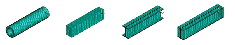
Figure 3. Solid finite element models.
Results for Solid Models
Table 1 illustrates, qualitatively, what an engineer already knows – the axisymmetric circular section did not warp, the solid rectangular section warped but those warping distortions were significantly less than for the open I-shaped section. The values for free warping agree well, exact for the circular and rectangular sections, with values of the theoretical, closed-form solutions.
Table 1. Stiffnesses for three sections (kNm/rad).
Given the degree to which restraining the warping of the I-beam increases the stiffness, it is not surprising to see that the addition of integral end plates will have a similar but partial effect (Table 2). For this example, the stiffness is increased by a factor of nearly three over the standard I-beam.
Table 2. Stiffness for the I-shaped section with and without end plates (kNm/rad).
Figure 4 shows contours of axial displacement together with the maximum value of axial displacement computed, rounded up to the nearest micrometer. Symmetric contour ranges were chosen, with red indicating +ve displacement and blue –ve displacements. For the prismatic members (those without end plates) with unrestrained warping, the longitudinal distortion of the cross-section is invariant along the element axis and exhibits the typical warping distribution with opposite signs at adjacent corners of the section. When warping is restrained, member warping still occurs away from the ends but has to transition to zero at the ends of the member.
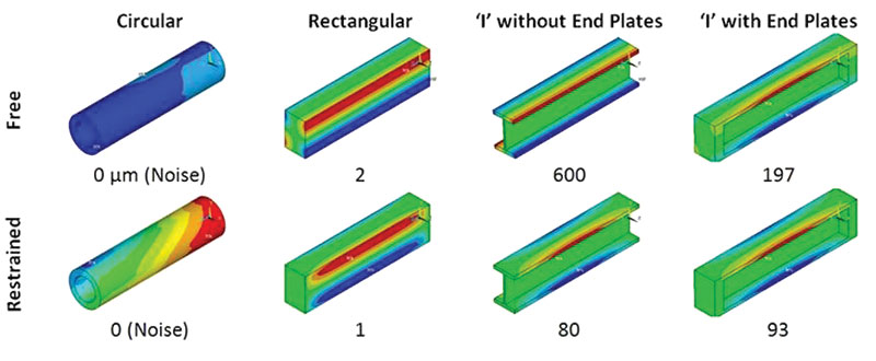
Figure 4. Contour plots of axial displacement (maximum values in μm).
Results for Beam Models
BEAM188 has two formulations; one which does not explicitly include warping and one which does. For the formulation that includes warping, an additional warping freedom is added to each node. An extract from the ANSYS Help Manual is shown in Figure 5 together with the corresponding dialogue box for setting the element’s Key Options.
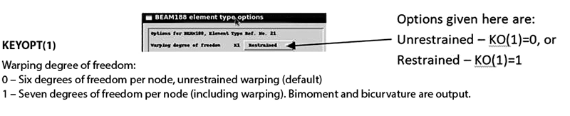
Figure 5. BEAM188 key options.
The following definitions are adopted to aid in understanding the beam formulation:
KO(1) = 0 – standard (default) formulation without warping freedoms
KO(1) = 1 – formulation with warping freedoms
For KO(1) = 1 – the nodes have additional warping freedoms which may be unrestrained or restrained
KO(1) = 1f – formulation with warping freedom unrestrained
KO(1) = 1r – formulation with warping freedom restrained at the ends of the model
The default formulation in ANSYS is KO(1)=0, but for sections that are recognized as open ANSYS provides a warning that the user should consider using KO(1)=1, presumably with the appropriate constraint of warping freedom. Table 3 lists the stiffness for the beams with the value in brackets equal to the percentage increase over the values obtained for the corresponding solid model.
Table 3. Stiffnesses for three sections (beam elements).
While there is a difference between the stiffnesses of the beam and solid models, with the beam models tending to be stiffer than the solid model, the results are consistent and, with no greater than a 5% difference, can be considered to be within reasonable engineering approximation.
The results for KO(1)=0 and KO(1)=1f are identical. This reminds us that the formulation without explicit warping (KO(1)=0) actually models free warping. It is also seen that the ANSYS dialogue box is misleading since, with KO(1)=1, the warping remains unrestrained until the user changes the default free warping freedoms.
The results for the I-section are compared in Table 4. Again, the numbers in brackets are the percentage change in stiffness compared with the solid model. Note, however, that for the beam with end plates, the beam model is now less stiff than the solid model.
Table 4. Stiffnesses for ‘I’ section with and without end plates (beam elements).
The second row of Table 4 is for the member including end plates. The first point to note is the massive discrepancy between the results for the KO(1)=0 beam model and the solid model with free warping. The explanation is that this beam formulation does not ensure continuity of warping between beams (there are no warping freedoms). As such, the partial restraint on the warping expected (and seen for the solid model) is not captured. The beam formulation KO(1)=1f offers a far more realistic solution as it is only 2% less than the result of the solid model. For the beam with restrained warping (KO(1)=1r), the stiffness increases but significantly less than that for the solid model and the stiffness is underestimated by some 20%.
Conclusions
The results for the I-beam are summarized in Figure 6 which shows that the basic beam element, without warping control, is clearly unsuitable for modeling situations where warping is partially or fully constrained. The more advanced element, which includes warping control, performs significantly better, particularly when end plates are not included. When end plates are included, the advanced beam model can lead to error. However, for the geometry considered in this article, the free warping case produces a good correlation with the solid model.
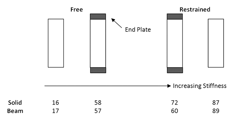
Figure 6. Summary of stiffnesses for the ‘I’ section.
The machined member in this study is to be bolted to thick members. So, it is likely that warping at the member ends would be almost entirely restrained by the adjacent structure. As such, if the member had been modeled with beam elements without warping restraint then the stiffness would have been underestimated by some 72/16=4.5 times! Although, when warping is restrained, the beam model still underestimates the stiffness but by only 72/60=1.2 times.
The error in the results shown above for beam elements reminds us of the importance of considering the appropriateness of the choice of idealization carefully. The sort of study presented here is thus necessary if the engineer is to make a sound, evidence-based decision as to the nature of the idealization to choose. An alternative approach, which may have both simplified the analysis and led to more reliable results, would have been to replace the I-sections with circular sections for which warping would not have been an issue. This indicates the potential virtue of adopting a ‘design-for-analysis’ philosophy which, particularly for one-off structures, has many potential virtues. Unless the torsional stiffness is captured in a realistic manner, natural frequencies involving torsional modes of deformation in a member will be poorly approximated which could be important, particularly if the structure is to be seismically qualified.
The absence of suitable benchmark verification problems for warping in beam finite elements provided part of the motivation for writing this article. In this study, it was found that the dialogue for setting the element Key Options in ANSYS was highly misleading. It suggests that warping is restrained when, in fact, it is not without further user intervention. The default option for BEAM188 is KO(1)=0. This, however, is only appropriate for axisymmetric cross sections. As such, a more appropriate default might be KO(1)=1 which, of course, should also apply to non-warping axisymmetric cross sections. The following recommendations are therefore suggested to ANSYS Inc:
1) Change the dialogue text from ‘Restrained’ to ‘Included’,
2) Add some benchmark examples and advice to the Help Manual, and,
3) Change the default value for KO(1) from 0 to 1.▪
This article was originally published in the NAFEMS Benchmark Magazine (July 2014). It is reprinted with permission.
Post Script
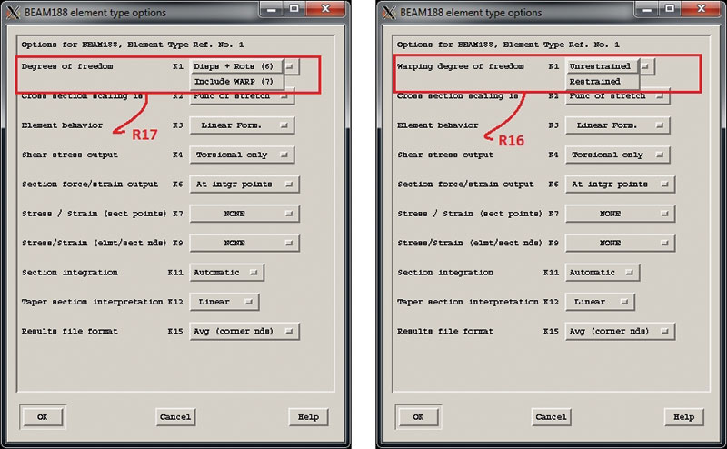
Following the publication of this article in the NAFEMS Benchmark Magazine (July 2014) ANSYS acted on one of the recommendations that was made by modifying the element type options dialogue for BEAM188:
References
[1] Timoshenko, S.P., History of Strength of Materials, Dover (1983) – ISBN 0-486-61187-6
[2] Hearn, E.J., Mechanics of Materials, Pergamon (1985) – ISBN 0-08-030529-6
[3] www.ramsay-maunder.co.uk/downloads/warping_article_web.pdf
[4] Hicks, S., Design of Members Subjected to Torsion, AD249, Steel Construction Institute