
A box beam configuration may be used at openings in a floor or wall framing assembly. The American Iron and Steel Institute’s AISI S100 contains design provisions for built-up flexural members consisting of two C-sections oriented back-to-back to form an I-shaped section, i.e. Section D1.1, but does not contain design guidance for a box-section formed by orienting two C-sections lip-to-lip. For built-up members to act as a single composite unit, the members must be connected with sufficient fasteners at the maximum spacing as calculated below. This article illustrates the extrapolation of S100 Section D1.1 provisions to a box beam configuration.
The AISI S100 provisions are based on stabilizing the shear flow in the flanges. The same shear flow exists in a box-shaped section; therefore, the S100 provisions could apply to form a box-shaped section with the two C-sections oriented lip-to-lip.
The AISI S100 provisions for Flexural Members Composed of Two Back-to-Back C-Sections (D1.1) are as follows:
The maximum longitudinal spacing of connections (one or more welds or other connectors), smax, joining two C-sections to form an I-section shall be:
smax = L/6 or [pmath]{2gT_s}/mq[/pmath], whichever is smaller (Eq. D1.1-1)
where
L = Span of beam
g = Vertical distance between two rows of connections nearest to top and bottom flanges
Ts = Available strength [factored resistance] of connection in tension (Chapter E)
m = Distance from shear center of one C-section to mid-plane of web
q = Design load [factored load] on beam for determining the longitudinal spacing of connections.
The D1.1 provisions, Eq. D1.1-1, define the fastener spacing along the length of the member (Figure 1).
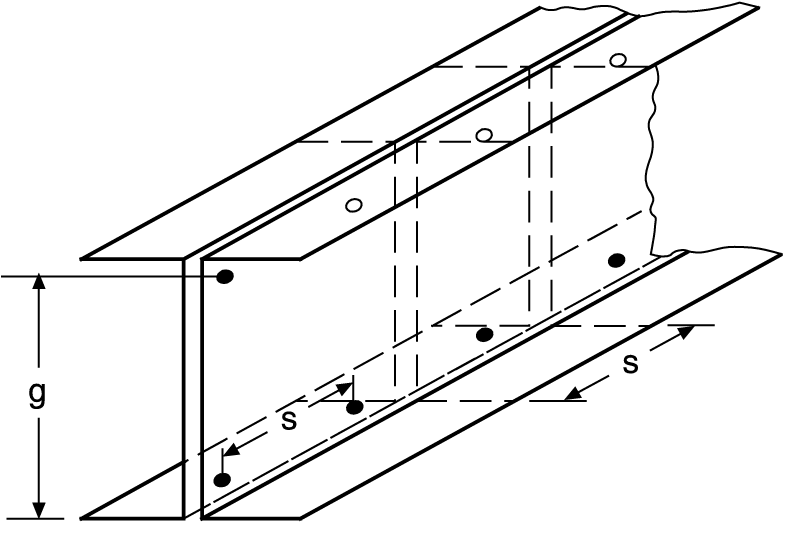
Figure 1. Figure C-D1.1-2 (AISI S100C).
Because the current D1.1 provisions are intended to stabilize the C-section and achieve equilibrium of the cross section for the single C-section (Figure 2), the D1.1 provisions may be adapted to box-shaped sections by recognizing that “g” is the vertical distance between the two rows of welds that interconnect the two C-sections. To evaluate “Ts”, the available strength of the welded connection, the provisions of AISI S100 Section E2.6, Equation E2.6-1, for flare groove welds applies. Using ASD, the safety factor is 2.55, and the nominal strength is as follows:
Pn = 0.833 t L Fu (Eq. E2.5-1)
Where, t is the thickness of the C-section, L is the length of the weld and Fu is the tensile strength of the C-section.
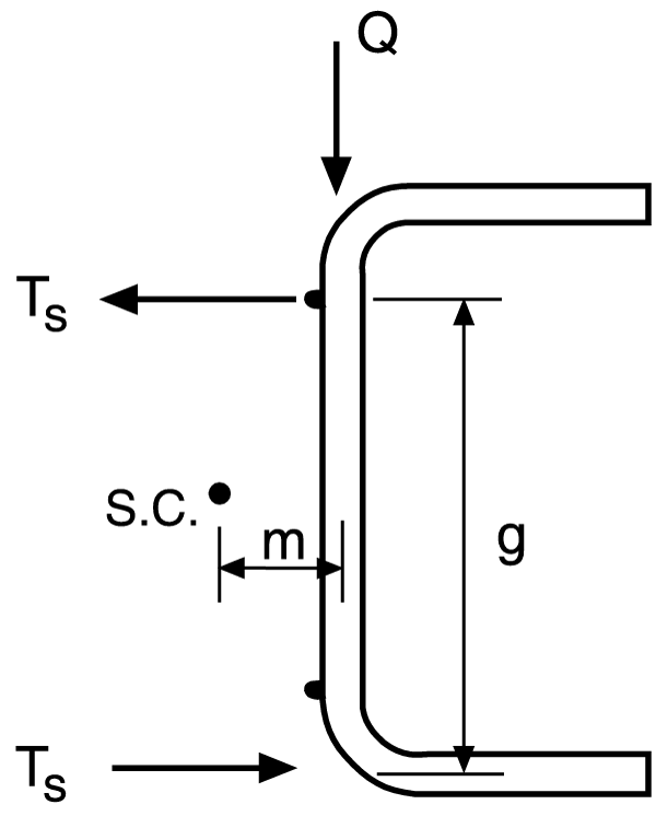
Figure 2. Figure C-D1.1-1 (AISI S100-07C).
Additional limit states that must be considered in the design of a flexural member are further defined in the AISI S100 provisions and include Bending, Shear, Combined Bending and Shear, Web Crippling, and Combined Bending and Web Crippling.
The following example illustrates the design steps for a built-up box beam.
Check Bending Alone (Section C3.1.2.2):
The two interconnected C-sections are assumed to behave as a closed box member. Because for a closed box member in bending, lateral buckling is unlikely, the AISI Specification first requires the evaluation of the critical unbraced length for which overall buckling is not a limit state. This design check is achieved by evaluation of the following equation:
Lu = [pmath]{0.36C_b pi}/{F_y S_f}[/pmath] [pmath]sqrt{EGJI_y}[/pmath]
If the span length is less than Lu, no intermediate braces are required to achieve the yield moment as computed by Section C3.1.1 of the AISI specification, Maxo = Sxe Fy / Ω
Check Shear Alone (Section C3.2):
For cold-formed steel members, shear alone is typically not a controlling limit state. However, the available shear capacity per web may be computed based on the limit states of shear yielding, shear inelastic buckling or shear elastic buckling. Because of the thin web material, buckling is the controlling shear limit state.
Combined Bending and Shear (Section C3.3):
For continuous span members, the combination of high shear and bending stresses may occur at intermediate supports. Thus, this limit state is an important design check for continuous span beams.
Web Crippling Alone (Section C3.4):
If the box beam is uniformly loaded, web crippling need only be considered at the end support. Web crippling must be considered if the box beam is supported on its bottom flange, and no web stiffener or clip is provided at the support location.
When checking web crippling, AISI Eq. C3.4.1-1 is applicable. The appropriate coefficients and safety factor are provided in Table C3.4.1-2. The coefficients and safety factor tabulated in Table C3.4.1-1 are not appropriate because these coefficients, although indicated to be valid for “built-up sections,” were experimentally developed for only I-shaped sections.
Combined Bending and Web Crippling (Section C3.5):
For continuous span members, the combination of high compression stresses resulting from concentrated loads and bending stresses may occur at intermediate supports. Thus, this limit state is an important design check for continuous span beams.
Check the Interconnection of the Two C-sections (Section D1.1):
To interconnect the two C-sections forming a box beam configuration, flare groove welds are commonly used to interconnect the flanges (Figures 3 and 4).
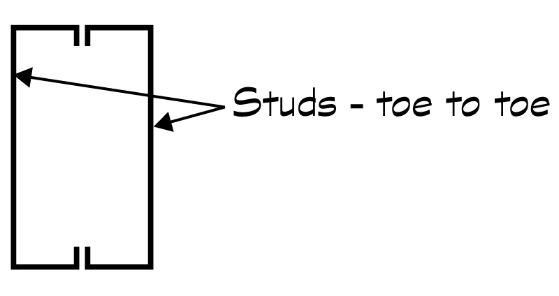
Figure 3. Typical box-shaped cross section.
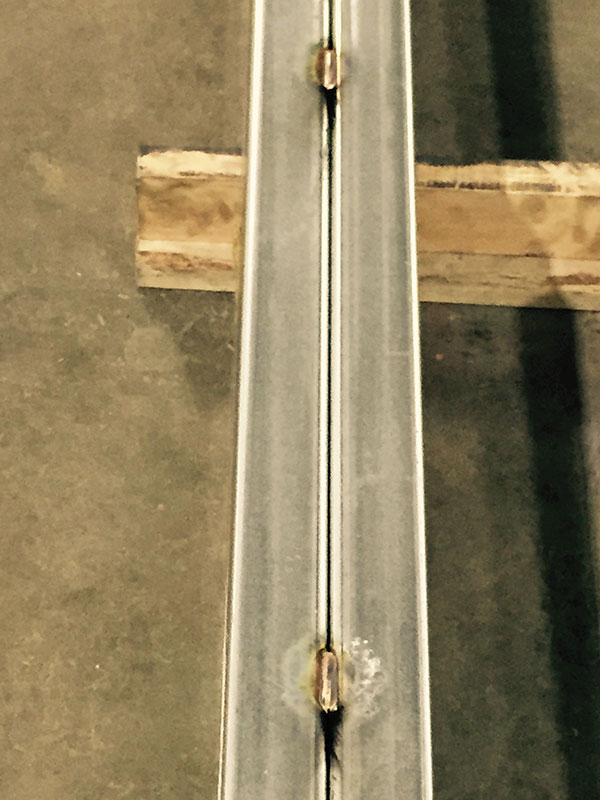
Figure 4. Typical groove weld.
The available strength of a flare groove weld can be computed using AISI Section E2.6.
The maximum longitudinal spacing for the welds, smax, as defined by AISI Section D1.1 is the lesser of
smax = L/6 or [pmath]{2gT_s}/mq[/pmath] (Eq. D1.1-1)
Although not required by Section D1.1, it is suggested that the maximum unbraced length, Lu, to achieve the yield moment, Maxo, for the single C-section be considered. The author suggests that Lu is considered to ensure that the weld spacing is less than the unbraced length to preclude overall buckling of the single C-section between the welds. The AISI S100 Commentary provides an equation for Lu (Eq. C-C3.1.2.1-11). The evaluated Lu should be greater than smax.
For a numerical example problem illustrating the design of a welded box beam, refer to Cold-Formed Steel Engineers Institute TN G104-14. For a numerical example problem illustrating the application of Section D1.1 for a back-to-back configuration, see page 303 of Cold-Formed Steel Design (Yu and LaBoube, 2010).▪
This article was originally published in CFSEI Tech Note, July 2014, Welded Box Beam Flexure Design, and is reprinted with permission.
References
AISI S100-12, North American Specification for the Design of Cold-Formed Steel Structural Members, American Iron and Steel Institute, Washington, D.C.
AISI S100-12C, Commentary on North American Specification for the Design of Cold-Formed Steel Structural Members, American Iron and Steel Institute, Washington, D.C.
CFSEI TN G104-14, Welded Box-Beam Flexure Design, Cold-Formed Steel Engineers Institute, Washington, D.C.
Yu, W.W. and LaBoube, R.A. (2010), Cold-Formed Steel Design, 4th Edition, John Wiley, NY