
How wind tunnel shaping workshops have become an invaluable tool for architects and engineers in search of high rise buildings’ optimal form.
Today, a great deal is known about how wind affects tall buildings differently than it does shorter structures. However, wind-related design issues are usually considered much later in the design process than they should be to achieve structures that have optimal performance with minimal cost. Wind engineers traditionally interact with structural engineers after the conceptual design phase when basic decisions about the building form and structural system have already been made. A better approach is to bring the entire building team up to speed on potentially challenging wind effects very early and resolve them when the design is still malleable. Early efforts have proven to be highly advantageous for some of the world’s tallest buildings, discussed later in this article.
Basic Aerodynamics of Buildings
Structural engineers who design tall buildings understand that the wind’s effect on a tall, slender structure is much more complex than just the effect of wind on a sail. Differences in complexity are due in part to differences in the load-resisting behavior of squat structures compared to slender structures, but it is also influenced by the different aerodynamics of these structures and their dynamic response.
For many buildings, a good initial design can be developed using the building code. The structural engineer then typically relies on wind tunnel testing for fine tuning the final design. However, as buildings increase in height, their dynamic response becomes more significant which makes them much more challenging from a structural design perspective. Code based calculations may not be such a good initial guide.
One consideration is the building’s aspect ratio, which reflects its slenderness. There are codes of practice that suggest any structure with a height-to-width aspect ratio over 4:1 or 5:1 would be sensitive to wind effects. Many of the buildings that have benefited from in-depth wind tunnel testing have aspect ratios of 10:1 or 12:1, values well beyond a code’s applicability. With such high slenderness ratios, the structure has a very high degree of flexibility, which also means it has long periods of vibration. Generally speaking, structures with longer periods of vibration attract more energy from the wind, which increases their motion during a windstorm.
Crosswind effects can also be significant. Shorter, squatter buildings tend to be dominated by wind induced drag, so the form drag of the building is what governs the loads. However, for tall structures, crosswind excitation becomes more important. These effects also can vary a great deal, based on the plan geometry of the building.
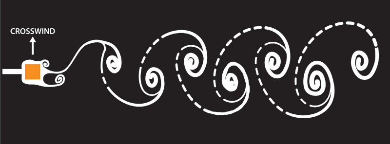
Figure 1. Sketch showing vortex shedding flow patterns. These regularly spaced vortices generate their largest forces perpendicular to the direction of flow, causing crosswind vibrations.
In essence, as the wind passes a building it generates a wake, which results in a fairly organized pattern of vortices being shed downstream (Figure 1). Tall and slender buildings with longer periods of vibration are more susceptible to the forces generated by that wake. Again, unlike the drag loading on a sail, these organized wakes generate their largest forces at 90 degrees to the direction of the wind. Because these forces are generated in an oscillating pattern, the structural loading may be amplified due to resonance.
The strength of the crosswind force is related to the plan geometry of the building, as well as the variation of geometry with height. Very prismatic buildings that show little variation in the plan form with height are the most susceptible to crosswind-induced motion.
Strategies to reduce these wind-induced motions include tapering structures and changing the plan form with height. Plan form changes can be things like changing building corner geometry or introducing apertures – or holes – into the structure. Any number of modifications can have beneficial effects. For example, introducing slots at building corners may provide some pressure relief. The challenge is putting potential improvements on the table, finding mitigating shape adjustments or other changes acceptable to the architect, and then working through them to determine what is optimal for the structure.
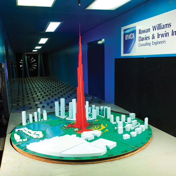
Figure 2. Burj Khalifa wind tunnel model. Stepped setbacks into the building were introduced, and the base was rotated to improve its aerodynamic efficiency in the direction of strongest winds.
A Little Expertise to the Rescue
Experience is a great teacher and, as a result, engineers specializing in wind design have developed in-depth expertise in this field. RWDI, one of the several firms specializing in wind engineering, has served as the Wind Engineer on many of world’s tallest buildings since its founding in 1986 – including record-breaking Petronas Towers, Taipei 101, the Burj Khalifa and the Shanghai Tower.
At 2073 feet (632 meters), the Shanghai Tower is China’s tallest building and the second tallest in the world. The design team wanted to build a twist into the building’s form, in addition to a tapering with height. The question was a matter of how much. The optimal form was found by testing more than 12 options that looked at different rotations of the building floorplan with height as well as the building’s orientation relative to the strongest winds. The final selected design reduced wind loads by 24 percent. This, in combination with an optimized structural design, resulted in significantly reduced material costs.
Wind engineering for the 2716-foot (828-meter) Burj Khalifa, in Dubai, United Arab Emirates, had an even greater benefit. The original design had been based on a much shorter building, similar in basic concept to the final product but approximately 984 feet (300 meters) shorter. Construction had already begun on foundations based on the original design, but the project goal changed while it was still under construction. Through the process of optimizing the shape for the wind loading, which included introducing stepped setbacks into the building and rotating the base to improve its aerodynamic efficiency in the direction of strongest winds, the building team was able to construct a much taller building that still had the same wind loads at its foundation level.
Much like the insights and technology from Formula 1 racing makes their way into the design of more common automobiles, these and other experiences designing super tall buildings have enabled the development of a shaping workshop approach for the optimization of more common tall structures. Formally launched at RWDI in 2012, the shaping workshop brings together the key players in the design team – the architectural designer, structural engineer, wind engineer, and owner’s representative – and typically accomplishes in a day or two what used to take months. The keys to success are today’s enabling technologies and the design team’s willingness to come together to participate in the workshop.
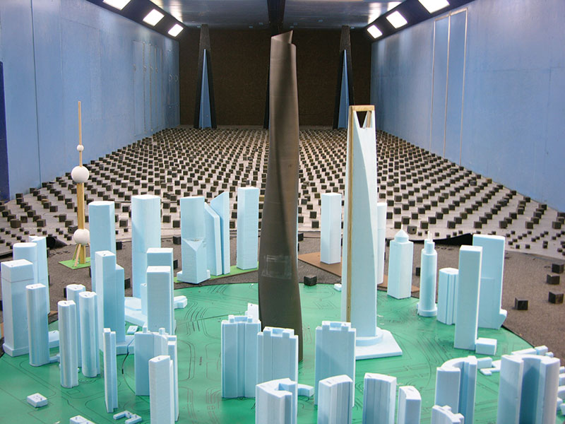
Figure 3. One of the prototype shapes that was explored for the Shanghai Tower before selecting the final design. This option has a 180-degree twist
as it rises.
How it is Done
Although the shaping workshop is best held as early as possible in the design process, it frequently is convened after a competition has established a base architectural form for the building. The owner likes the design, the architect obviously has some passion for it, and the structural engineer has developed a baseline structural system.
That is when wind engineers are brought on board to do a first wind tunnel test of the proposed structure. The test simulates the airflow associated with the atmospheric boundary layer and the localized influence of surroundings to identify the wind forces on a scale model. Using the most common approach, the high-frequency-force-balance technique, data collected from the simulation are combined analytically with the structure’s dynamic properties to determine its wind-induced motion.
Particularly with tall and slender buildings, this motion is a governing factor in the design of the structure. Building deflections affect the overall serviceability of the building with respect to façade performance and other items such as interior partitions, so general guidelines have been established to limit the deflections of the building. However, occupant comfort is the more significant design challenge for most tall buildings. Through experience, wind engineers have established benchmarks of acceptable magnitudes of building motion considering their effect on occupants. It is not unusual for the first wind tunnel test to reveal that the architectural design sits well above those criteria.
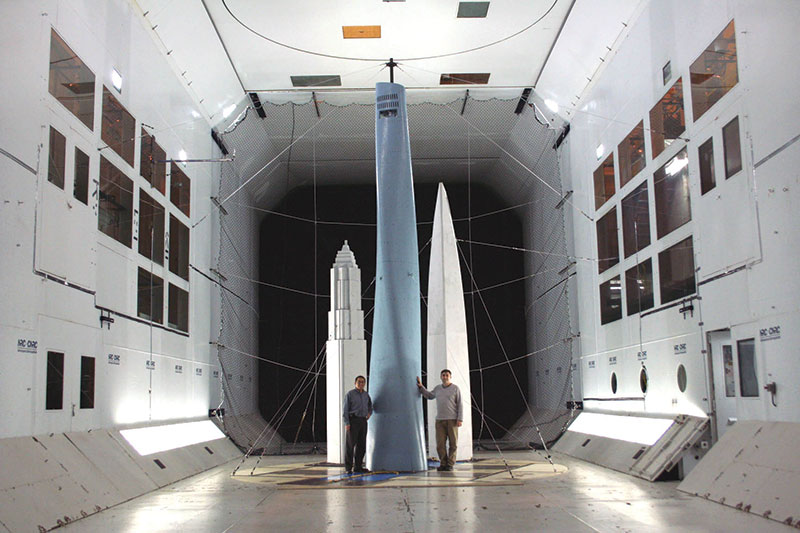
Figure 4. Large scale wind tunnel testing of the Shanghai Tower. The final design has a 180-degree twist as it rises and its base is rotated to be aerodynamically efficient in the direction of the strongest winds.
The goal is then to get within these benchmarks through design modifications. One option is to make slight modifications to the architecture that can yield large aerodynamic improvement, such as rounding the corners or introducing some taper into the building. Another approach is to determine how sensitive the motion is to the structure’s natural periods and identify ways to move the needle in a positive direction. A third alternative is to look at the building’s natural ability to dissipate energy, i.e., its damping capability. Often it is feasible to add supplemental damping into the building and enhance performance in that way.
In the context of a shaping workshop, these discoveries occur in real-time when the design team is together. After that first evaluation to quantify the scope and scale of the challenge, the wind engineers typically suggest modifications to the architecture that would result in certain benefits. These suggestions inevitably lead to a discussion – some suggestions are palatable, some are not.
The opportunity for real-time feedback and collaboration is one of the most significant benefits of having the design team all together. For example, there may be a suggestion to modify a particular aspect of the design that the architect does not want to change. In this type of forum, they can explain their architectural passion about the item, which enables others on the team to better understand the architectural perspective.
There also may be economic drivers to consider. The building may have a particular shape or orientation because it lends itself to a better unit layout, or it may be oriented a certain way to maximize views – for example, overlooking New York’s Central Park. With such considerations on the table, there is typically a good discussion resulting in a few options to be considered. At that point, it is back into the wind tunnel to quantify the benefit of those different changes to the shape.
Fortunately, advances in rapid prototyping now permit testing of numerous models cost-effectively and in rapid succession. In one day at a recent shaping workshop, the team ran through a series of 10 different iterations in succession, each showing slight improvements over the others.
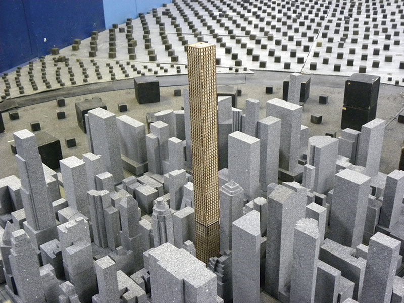
Figure 5. Initial wind tunnel model of 432 Park Avenue that was tested before the exploration of openings in the shaping workshop.
A Challenging Structure in NYC
One of the more challenging and creative recent applications of wind engineering expertise is nearing completion in the form of 432 Park Avenue. This 1396-foot (426-meter) structure in the center of Manhattan is the tallest residential tower in the western hemisphere and the third tallest building in the U.S.
Architect Rafael Viñoly’s vision for the tower was pure prismatic form, something that was very compelling for the owner as well. It was meant to be this square shape, extruded straight into the sky, the exposed concrete expressing structure in a pure and simple elegant form.
When RWDI’s wind engineers began working with the architect and the structural engineer, WSP Cantor Seinuk, part of their job early on was to educate the rest of the design team on the special challenges in this tall, slender, prismatic structure. Its dynamic properties, when combined with the site’s known wind characteristics, meant that about once a month the wind speed would cause a significant wind-induced motion. That type of event is similar in magnitude to a once a year event in more traditional structures, but this building would get into this resonant condition with the wind fairly frequently.
That was new and somewhat unexpected territory for the design team to consider. Recognizing the comfort of occupants is the factor that is most critical, the team had to set the limits of motion – and more importantly of acceleration – to be achieved.
There are well-established criteria based on a great deal of practice working on more conventional structures over the years. However, they are based on the assumption of infrequent wind-induced motion. On this project, they would be much more frequent, if not the norm, for some periods of time. The traditional ways of thinking about wind effects and the rules of thumb normally used didn’t apply in this case, which meant rewriting the rulebook.
The design team looked to a marine simulation center in Newfoundland for a better understanding of the problem. This group’s unique motion simulator is designed to help train marine captains. Because the natural frequency of the 432 Park Avenue tower aligns fairly well with the period of ocean waves, the facility could easily simulate the sort of motion predicted for the structure.
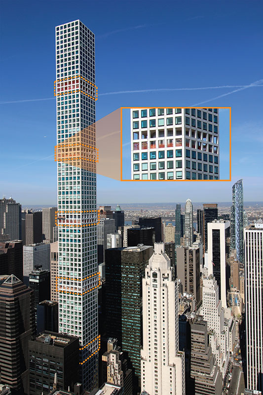
Figure 6. 432 Park Avenue with double story openings at five levels.
First, the standard rules of thumb were translated into a motion simulation that could be experienced by the design team. The simulation replicated the building response during a wind event at the more frequent occurrence levels anticipated. Next, the design team – the architect, the structural and wind engineers, and the owner – went through a series of exercises to experience the actual predicted motions that occupants would feel in the building, looking at different scenarios for mitigating that motion. It was an exercise in translating rules on the page – the benchmark values gleaned from years of experience – into rules based on simulations of the occupants’ anticipated experience.
After an early study had quantified the wind-induced motion, there was an acceptance and understanding among all members of the design team that they would have to look to tuned mass dampers and other technologies to make the project a success. With the limits of motion coming out of the simulation experience, it became clear that the two 600-ton mass tuned dampers already planned for installation at the top of the tower would not be sufficient working on their own. It was time to address architectural modifications.
The strong commitment of the architect and owner to maintaining a pure prismatic form led to a shaping workshop exploring the concept of opening up some of the floors to allow wind to pass through the building and break up the coherence of the vortices.
Ultimately, opening up two adjacent floors at five locations evenly spaced throughout the building’s height was found to be the optimal arrangement. Working in concert with the tuned mass dampers, this achieved the necessary reduction in wind effects on the structure without compromising the architectural expression.
Conclusion
Wind effects are undoubtedly forces to be reckoned with, especially in designing tall, slender structures. Using an orderly and rational approach, such as a shaping workshop, addressing wind-related concerns early in the design process enables all involved to push the limits of possibility while still producing a building that is comfortable, economical, and safe.
Project Partners
For the projects identified in this article, consulting engineering firm RWDI (Guelph, Ontario, Canada) worked in close collaboration with the respective design teams. For the Burj Khalifa, this included Skidmore, Owings & Merrill, who were the design architect and structural engineers for the project. For the Shanghai Tower, the design team included the design architect Gensler and the structural engineers Thornton Tomasetti. The design team of 432 Park Avenue included the design architect Rafael Viñoly Architects of New York City, WSP Cantor Seinuk, who was the structural engineer, and SLCE, the architect of record.▪
References
Irwin, P., Denoon, R., & Scott, D. (2013). Wind Tunnel Testing of High-Rise Buildings. Routledge. CTBUH in conjunction with IIT and Routledge / Taylor and Francis Group, Chicago.
ASCE 49-12 (2012) Wind Tunnel Testing for Buildings and other Structures American Society of Civil Engineers, Reston.