
This article is a follow-up to one of the precast, prestressed thin slab parking garage structures described in Precast, Prestressed Thin Slabs in Parking Garage Structures, published in the January 2016 issue of STRUCTURE magazine.
As a result of the findings of the previous investigation of the upper four levels of an existing six-story parking garage structure, and the identification of a significant number of unsafe prestressed slabs (planks) that had to be temporarily shored, Pennoni recommended that Non-Destructive Evaluation (NDE) of the first framed level be conducted. The purpose of the NDE was to determine if additional unsafe planks also existed at the lower level of the garage.
The NDE investigation was required because access to the underside of the framing at the lowest level of the garage was not practical or, in some cases, even possible. In addition, because all of the other unsafe planks in the upper levels of the garage were impacted primarily by corroded and or failed strands in the slabs, it was reasonable to assume that the lowest level of the garage (which is exposed to the most traffic from vehicles entering the facility immediately from streets treated with deicing salts) would also be adversely affected by strand corrosion. Because the ground floor spaces immediately below the first framed level could not be disturbed, the plank soffit cracking and spalling at corroded strands could not be easily observed or accessed for closer inspection. Therefore, it was necessary to use extraordinary means to detect any unseen strand corrosion from the driving surface of the first framed level.
Initial research into possible NDE resources first involved contacting Pennoni’s Intelligent Infrastructure Systems (IIS) Division, which performs NDE and installs a number of different types of structural monitoring systems for highway bridges. IIS indicated that, of the many NDE methods available, the best approach would be to use Magnetic Flux Leakage (MFL) to detect the presence of a loss of cross-sectional area of the strands. MFL involves magnetizing the embedded reinforcing and scanning the same areas to detect anomalies. Anomalies detected during the survey would be an indication of the likely section loss of a strand, which in turn would allow for the identification of areas of strands likely to be significantly damaged or completely consumed by the corrosion process.
Although IIS did not have access to MFL equipment, the Center for Advanced Infrastructure and Transportation (CAIT), Infrastructure Condition Monitoring Program (ICMP) at Rutgers University did have the recommended equipment. Dr. Nenad Gucunski, Ph.D., the ICMP Program Director, indicated that the MFL equipment at the CAIT did not have the capability to detect the strand, which was as deep as 5 inches from the top surface of the slab. He directed Pennoni to contact Dr. Al Ghorbanpoor, Ph.D., the Director of the Structural Engineering Laboratory at the University of Wisconsin-Milwaukee. After further discussions, Dr. Ghorbanpoor was subsequently retained for the MFL survey of the lower level of the garage.
Based on the results of the previous investigation of the upper levels of the garage, which revealed that corroded and failed strands had occurred predominately adjacent to the joints of the planks, the MFL scan was performed on each side of the plank joints. The approximate locations of the plank joints were determined based upon the location of the corresponding concrete topping control joints, which could be observed on the driving surface. The approximate total linear feet (LF) of joints located at the lower level of the garage was 2,500 LF; therefore, a total of approximately 5,000 LF of MFL scans were required.
Due to the presence of existing #5 top reinforcing bars in the concrete topping, which occurred parallel to and near the plank strands, it was not clear before the MFL survey was completed if it would be possible to magnetize and assess the condition of the underlying plank reinforcing. It was anticipated that the most likely area for potential interference would be above and near the existing steel beam supports. In addition, it was anticipated that the proximity of the vertical lattice or “filigree” reinforcement could also potentially make it difficult to identify the adjacent 3/8-inch diameter strand using the MFL system.
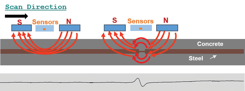
Figure 1.
MFL Investigation
A novel NDE method based upon the concept of MFL was used in the assessment of the prestressing strands in the thin precast concrete slabs in this parking garage structure. The MFL concept is based on detecting magnetic flux leakage in a magnetized strand where there is a loss of cross-sectional area. Figure 1 illustrates this concept as the response of a Hall-effect sensor signifies a section loss and its location in a strand or rebar embedded in concrete. Hall-effect sensors are transducers that produce a varying output voltage in response to a changing magnetic field. The sensor output, or the shape of the MFL signature, including its amplitude and period, is influenced by the size, configuration, and orientation of the section loss as well as the distance between the steel reinforcing and the magnetic sensors.
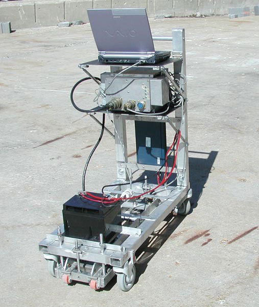
Figure 2
The primary components of the MFL system are two strong permanent magnets and a set of Hall-effect sensors that are installed in a testing cart to allow for portable testing of parking garages and bridge decks (Figure 2). The system is also equipped with an encoder device that allows recording of the precise location of each data point along the length of each scan. The system is designed to be durable for field use and requires only a small DC power source for its operation.
Before the MFL test at the site, a laboratory investigation was performed to verify the capability of the MFL system to detect section loss in steel strands. The MFL system was verified to have the capability of detecting losses exceeding approximately 40 percent of the cross-sectional area in strands and rebars that were located no more than five inches from the surface. Smaller cross-sectional area losses could not be detected reliably due to the depth of embedment and the effect of magnetic interference from other steel rebars within the garage slabs.
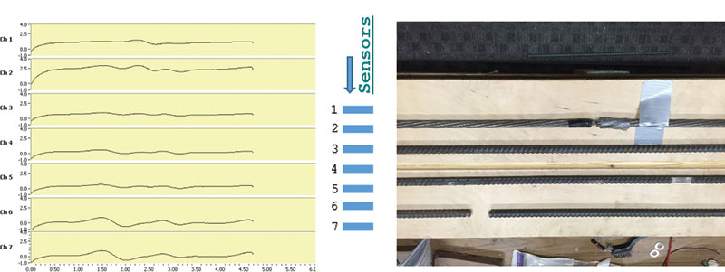
Figure 3.
Figure 3 illustrates representative laboratory MFL signatures from multiple side-by-side sensors (sensors 1 to 7 covering a width of 8 inches) for steel rebars and strands with varying cross-sectional area loss. These strands and rebars were located a distance of 5.5 inches from the top surface. Figure 3 indicates the scan length, in feet, and signal amplitude, in volts, along the horizontal and vertical axes, respectively. Note that the larger amplitude MFL signals from sensors 6 and 7 indicate a complete fracture in the lowest bar shown in Figure 3.
After the completion of the laboratory verification, the MFL equipment was transported to the site for field testing. Daniel Strohfeldt, an Electrical Engineering undergraduate research student at the University of Wisconsin – Milwaukee, assisted Dr. Ghorbanpoor with the field investigation. The system was used to scan the surface of the lowest framed level of the structure to assess the condition of prestressing strands in the thin precast slabs. The construction of the framed garage structure included a layer of concrete topping over the precast slabs. Each scan was made by moving the testing cart directly above a strand near the topping joint located above the precast slab joints below. The approximate location of each strand was marked on the garage deck with a chalk line before the start of the MFL tests, which was used to guide the direction of each test scan.
The field testing was preceded with an additional verification test on strands with known conditions (i.e., with and without corrosion) at the second framed level of the garage structure in which the precast slabs were visible from the level below. Figure 4 shows side-by-side representative graphs of the MFL tests for these strands, with the resulting data (i.e., amplitude vs. scan data position) indicating the strand conditions. The multiple peaks and valleys seen in the graphs are from the responses of the sensors due to the interference effects of crossing rebars in the concrete topping. The higher amplitude signals in the graphs are associated with the location of the steel beams supporting the precast slabs.
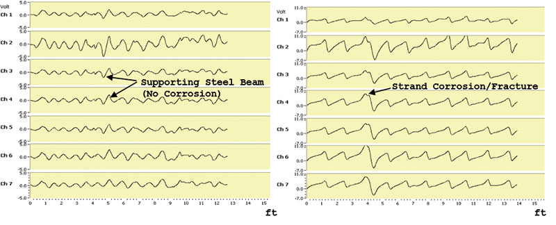
Figure 4.
The MFL test at the first framed level of the parking garage structure included a total of 106 scans along the edges of adjacent precast slabs. These tests were completed over a period of 1.5 days. The use of the MFL system in the garage structure allowed for a successful detection of corrosion in multiple areas. The MFL test scan locations, corroded strand lengths, and strand fracture for each strand were marked on the plan to aid the condition assessment of the garage deck (Figure 5).
As indicated in Figure 5, there is evidence of local and extended corrosion, as well as a partial or full fracture of the strands within the precast slabs for the first framed level of the parking garage structure. In total, the MFL test results indicated 37 partial or full strand fractures and 81 areas of local or extended strand corrosion. Using the results from the MFL tests, appropriate temporary support methods were designed and implemented by Pennoni Associates to extend the service life of the structure.
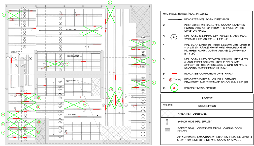
Figure 5.
Repairs
As previously indicated, the majority of the underside of the lowest framed level of the garage was not accessible. However, some areas of the framing were visible, but not easily accessible, from the ground floor loading dock and entrance ramp of the garage. Observations made of surface cracks and spalls in the soffit of the planks were used as the basis for confirmation of the conclusions of the MFL survey. Areas of strand section loss identified by the scans corresponded with the same areas of cracked and spalled plank soffit.
Fortunately, the majority of the unsafe plank locations identified by the MFL survey were above these same limited-access areas, which made it possible to install shoring beams rather than having to block off the same planks above from further vehicular access. The method of installing the shoring beams followed the previously established criteria used in the upper levels of the garage, which minimized the impact of the repairs on the operation of the facility. Unsafe areas that were not accessible, including parking spaces and a small area of the driving aisle, were permanently blocked off from further vehicular access via barricades that were attached to the concrete topping.
The design of the shoring beams was based on a tributary width of 2 feet, which corresponded to the strand edge distance from the plank joint of 3 inches and one-half of the uniform spacing of the strand within the plank of 18 inches on center, on each side of the plank joints. This allowed for the shoring beams to be located near the plank joint centerline, thereby providing support for the portion of both adjacent planks that had already exhibited, or had the potential to be subjected to, significant strand corrosion.
Conclusions
As a result of the overall investigation and temporary shoring of the garage at all five framed levels, and in acknowledgement of an estimated remaining service life of the structure of six to nine years (i.e. the point at which all planks would likely have to be shored), it was recommended to the owner of the facility that visual and exploratory demolition investigations of the accessible framed levels and MFL NDE, at the lowest framed level only, be conducted annually. Annual inspections would identify additional unsafe planks that needed shoring over the remaining life of the building. Based on the results of the additional future investigations, the owner plans on determining when it would be economical to demolish the existing structure and construct a new replacement garage.▪