
The authors recently conducted a study into the elastic behaviour of thin (Kirchhoff) plates using commercial finite element (FE) software. In attempting to verify the FE solution, it was compared to results presented in Timoshenko’s text and a significant difference was observed. This article presents the work conducted to uncover the reason for this difference and reveals an error (probably typographical) in the text. The source of the error is identified and it is demonstrated how such errors might propagate into other texts on the subject of plates. The significance of the error to the practising engineer is also discussed.
Plate Configuration
The plate considered is rectangular with an aspect ratio b/a. It is simply supported on two opposite sides and loaded with a uniformly distributed load (UDL) as shown in Figure 1.
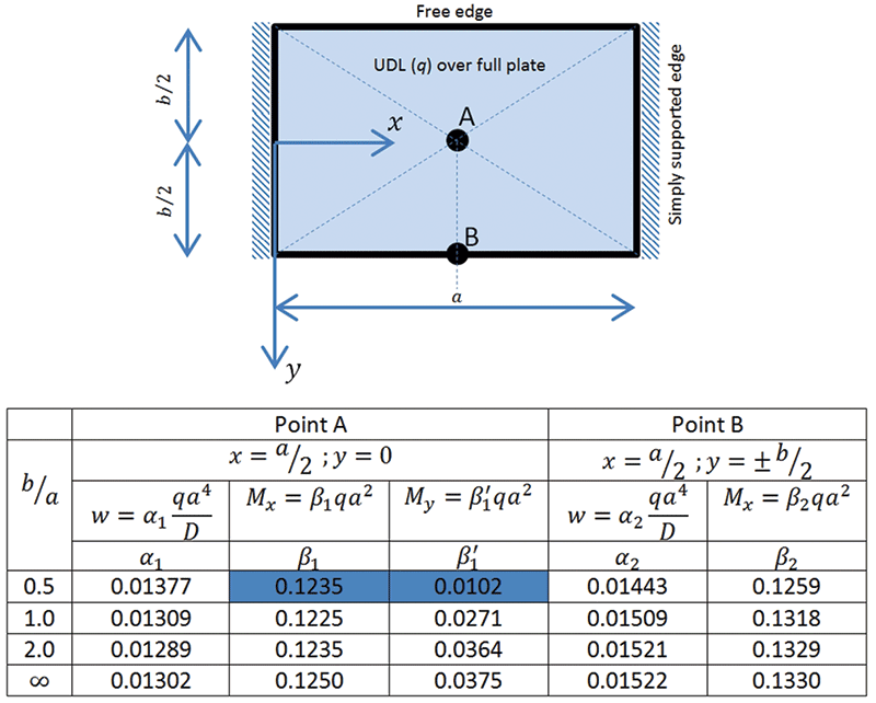
Figure 1. Plate configuration and Timoshenko’s results.
This problem is considered in Article 48 (p 214) of the Theory of Plates and Shells (Timoshenko, 1989) and the deflections and moments at points A and B are reported in the text (Table 47, p 219) for a Poisson’s ratio of v = 0.3. This table has been reproduced in Figure 1 where D is the flexural rigidity of the plate and w is the transverse displacement.

Figure 2. Moments and stresses at center of plate (point A) and definition of moment ratio.
In Figure 2, an infinitesimal region around the center of the plate is shown, together with the moments and stresses. The uniformly distributed load causes sagging moments in both longitudinal and transverse directions which induce stresses in the plate, linearly distributed across the thickness, as shown with the stresses on the top surface both being compressive. Note that the moment mx causes a direct stress in the x direction (σx).
Finite Element Analysis
The aspect ratio of the plate considered was 0.5 and the authors chose to study the convergence of the moment ratio (defined in Figure 2) with both mesh refinement and span to thickness ratio (a/t). The reason for considering convergence with span to thickness ratio was that the finite element system used only provided thick (Reissner-Mindlin) plates, and it was therefore necessary to ensure that the chosen thickness was small enough to have removed the influence of shear deformation which is not considered in the thin (Kirchhoff) formulation which is being investigated.
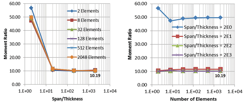
Figure 3. Convergence of moment ratio at point A with span/thickness ratio and mesh refinement.
The results from this convergence study are summarized in Figure 3, where an initial mesh of 1×2=2 elements was used with uniform mesh refinement. Span/thickness ratios between 2 and 2000 were studied. Both studies converge to a moment ratio of 10.19 as shown in the figure.
The ratio of the moments presented in Timoshenko’s text is 12.11, so there is a significant difference, approaching 20%, between the FE values and the published moments. This needs further investigation.
Development of a Computer Program
Timoshenko’s text provides an expression for the plate transverse displacement (w) as a single series (attributed to Levy and presented on p 217, eq(h)), which may be twice differentiated to produce the moments – see page 39 of Timoshenko’s text for example.
The expressions for the moments were coded into a small program so that they could be evaluated at a given point within a plate of arbitrary aspect ratio (b/a). The summation implied by the series solution is carried out in a loop for which only odd indices are considered and the upper value of the index is maintained as a variable in the program. Rapid convergence is observed with the moment ratio for 26 terms in the series being 10.17843 as shown in Figure 4.
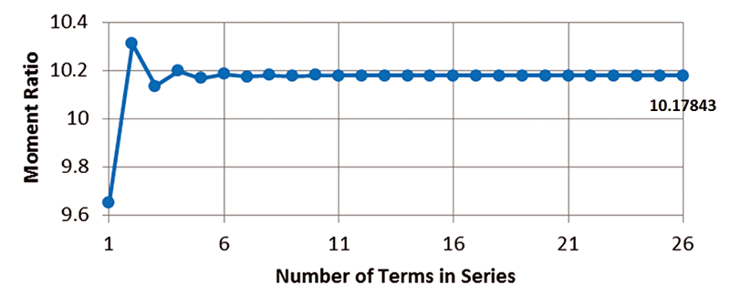
Figure 4. Convergence of moment ratio at point A.
The program produces values of displacement and moment at any point. These values may be used to plot distributions across the plate, and inspection of these distributions for satisfaction of the kinematic and static boundary conditions will provide verification that the program is correct.
The displacement field, not shown in this article for conciseness, demonstrates that the zero displacement condition along the simply supported edges is satisfied and that the field possesses the expected symmetry about the lines x = a/2 and y = 0.
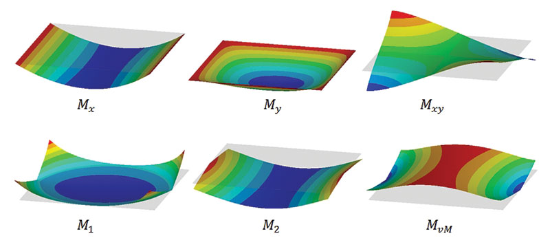
Figure 5. Moments from program.
The Cartesian components of moment are shown in Figure 5. The static boundary conditions require there to be zero bending moment along all edges, and this is clearly seen. The torsional moments are not required to be zero along the boundary, as Kirchhoff theory is assumed, but they should be zero along the two lines of symmetry and this is the case. The principal moments and the von Mises moment field, Mvm, are shown in the figure. The point of first yield is at point B, the center of the free edges.
An additional finite element result was produced using a pure Kirchhoff finite element. This gave a moment ratio of 10.1784 which, to four decimal places, is identical to that produced by the program, thus independently verifying the program. The moment ratios from the four independent sources considered are shown in Table 1.
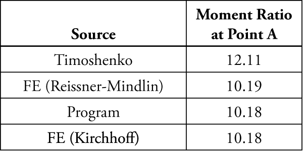
Table 1. Summary of moment ratios at point A from different sources.
The results shown indicate that there is something amiss with the values published in Timoshenko’s text, at least for an aspect ratio of 0.5, and further investigation of the individual moment components used in the moment ratio show that it is the value of My at point A which is in error, with the value in the text being 0.0102 and the value from the program being 0.0122.
The table of point results produced in Timoshenko (and reproduced in Figure 1) is attributed to a 1936 publication by D. L. Holl studying the problem presented in this article. In the era when the original publication was prepared, digital calculators/computers were not available and so it is likely that the moment values were calculated by hand, using tabulated data to obtain the hyperbolic trigonometrical functions and taking only a small (but presumably sufficient) number of terms in the series. The difference between the published values and those produced by the program is reasonably small for all but My for an aspect ratio of 0.5 as shown in Table 2.
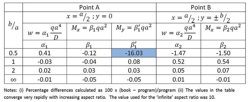
Table 2. Percentage difference in displacements and moments.
As already noted, the values of My at point A for the book and program are, respectively, 0.0102 and 0.0122. It is interesting to surmise that there is a typographical error in the book value, since if the last two digits are transposed then it becomes 0.0120 and the error reduces to -1.64% which is much more in line with the error in the other values reported in Table 2.
Practical Conclusions
This article has uncovered, by chance, an error in the published result for the transverse moment at the center of the plate configuration considered when the aspect ratio is 0.5. It illustrates the sort of care required by practicing engineers when taking published data at face value, even when it comes from such revered texts as Timoshenko’s. With the wide availability of finite element systems, the practising engineer can, and should, check the values he or she is going to use in the design or assessment of a structural member. It is also interesting to note the fact that published errors can propagate. In this case, erroneous data published in 1936 was still being used in the 28th reprint of Timoshenko’s text published in 1989 and also appears in Szilard’s 2004 publication on the theory and application of plate analysis (case number 103). The authors of this current article have contacted the publishers of 1989 printing of Timoshenko’s text regarding this error, asking whether it might be corrected at a future reprint. However, it is understood that no further reprints are likely. This raises the question of how one then might protect practising engineers against the propagation of erroneous published data. One way to do this would be to have an online repository of such errors which engineers can access to check that there are no reported discrepencies in the data they are proposing to use. In the absence of such a facility, the best one can do is publish the finding, as here, with the hope that it will reach the intended audience.
With regard to the engineering significance of this finding, the error leads to an under-prediction of the minor (transverse) component of the moment at the plate center. The engineer designing a steel plate might use the moments to calculate the von Mises moment and ensure that this is below the yield moment for the steel being used, since the von Mises moment is greater at the center of the free edge (point B) than at the center. Then, provided the engineer notices this, the erroneous value in the table would never be used. For a designer of a reinforced concrete slab, however, this number may well be used to size the reinforcement lying parallel to the y axis and an under-prediction of some 16% might lead to a situation where the structure is pushed out of the elastic region and into the plastic region. The degree to which this will occur should, however, be well within the ultimate capacity of the slab, but may be undesirable in terms of serviceability issues such as cracking of the concrete.▪
Acknowledgement
The authors would like to thank Professor J. P. B. M. Almeida of the Department of Civil Engineering & Architecture, IST, and University of Lisbon, Portugal for running the plate through his Kirchhoff equilibrium finite element software and Professor Husain Jubran Al-Gahtani of the King Fahd University of Petroleum & Minerals, Dhahran, in the Kingdom of Saudi Arabia for independently verifying the results produced by the program using Mathematica.
A similar article was published in the NAFEMS Benchmark Magazine, January 2016. Content is reprinted with permission.
References
S.P. Timoshenko & S. Woinowsky-Krieger, Theory of Plates and Shells, 2nd Edition, McGraw-Hill International Series, 28th Printing 1989.
D.L. Holl, Iowa State College, Engineering Experiment Station, Bulletin 129, 1936.
R. Szilard, Theory and Application of Plate Analysis, Wiley 2004.