
Increased availability of cross-laminated timber (CLT) in North America, combined with successful use in projects worldwide, has generated interest in its properties and performance within the U.S. design community. With the inclusion of CLT in the 2015 International Building Code (IBC) and 2015 National Design Specification® (NDS®) for Wood Construction, curiosity is evolving, with some developers, architects and structural engineers using CLT in projects. One application under frequent consideration is the use of CLT within horizontal floor and roof systems to create long-spanning structural decks. This article covers the available U.S. design standards and methods being used by engineers on these projects.
CLT in North America
Cross-laminated timber is an engineered wood component manufactured from dimension lumber or structural composite lumber to create large, flat panels of solid wood. It is a member of a new class of massive (or “mass”) timber products – i.e., large-dimension engineered structural wood components that complement the dimension sawn lumber, solid sawn timbers, and structural composite lumber products frequently used in building framing. Other forms of mass timber construction include nail-laminated timber (NLT), glued-laminated timber (GLT) panels and solid panels of structural composite lumber materials. The large component sizes and strength of the mass timber panels allow these structural components to be an alternative to concrete, steel and masonry components in many building applications.
In North America, the availability and acceptance of CLT are relatively new; however, adoption is happening quickly considering the speed at which material design standards and building code modifications typically occur. The ANSI-approved product standard, ANSI/APA PRG 320 Standard for Performance-Rated Cross-Laminated Timber, provides a basis for standardization of CLT quality, manufacturing and structural properties for structural building applications in North America. Currently, there are three North American manufacturers of CLT with manufacturing certified to the ANSI/APA PRG 320 standard: Nordic Structures, Structurlam Products, and DR Johnson Wood Innovations. Additional companies are expected to begin manufacturing CLT for building applications shortly.
The size of manufacturing equipment and shipping constraints limits CLT panel sizes. North American-manufactured CLT is available in panels as large as 8 feet by 40 feet. While CLT is shipped anywhere in the U.S., it is not a “stock” product with material sitting at a local distribution center; panels are manufactured for specific projects. Design teams considering using CLT should work closely with manufacturers to understand availability and lead times. With extended lead times, importing CLT from overseas, notably Europe, is also possible.
CLT panels can be used in floor, roof, and wall framing. There are cases where buildings were constructed using CLT for all of the structural framing above the foundations, including walls, floors, and roofs. Other buildings use CLT for specific structural components such as floor decking.
U.S. Design Standardization
A foundational document for designers using CLT in North America is the U.S. CLT Handbook, available free. This Handbook covers a spectrum of topics relevant to the design of buildings using CLT, including structural properties, connections, enclosures, acoustics and fire performance. While not referenced by the building codes, this document provided a basis for early U.S. CLT applications through alternative means processes.
Building on and updating the structural provisions of the CLT Handbook, the building code-referenced 2015 NDS includes a new Chapter 10 covering engineering design of CLT. The NDS now includes provisions for dowel-type fasteners into CLT in Chapter 12. The calculated fire-resistance method of wood members in Chapter 16 of the NDS includes provisions to calculate up to a 2-hour structural fire-resistance rating of loaded CLT members. The calculated fire-resistance rating of CLT is based on ASTM E119 fire tests of structural CLT. For further information on the 2015 NDS changes, see the Code Updates article from the January 2015 edition of STRUCTURE.
Product quality and engineering standardization enabled explicit recognition of CLT in the 2015 IBC. CLT is identified as a structural material, defined in IBC Chapter 23 with reference to the PRG 320 standard and the 2015 NDS. CLT framing is allowed within Construction Types III, IV, and V, and for roof members in Types I and II roof assemblies requiring a 1-hour fire-resistance rating or less. IBC provisions for Type IV define minimum CLT material thickness for the use of CLT as a Heavy Timber floor (4 inches) and roof (3 inches).
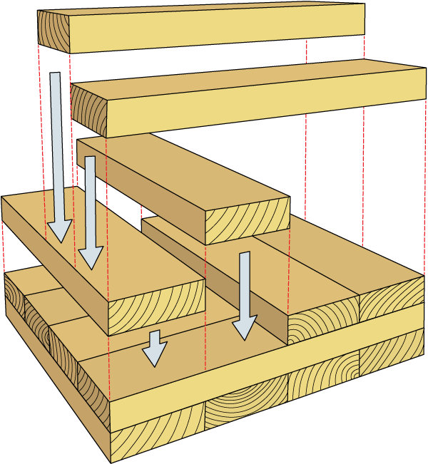
Figure 1. CLT layup.
CLT Manufacturing
CLT is manufactured from dried dimension lumber with adhesives applied between laminations, similar to glulam members. As with plywood, CLT typically has an odd number of layers. The exterior layers are parallel and create the strong direction of a panel while perpendicular interior-only layers define its relatively weaker direction (Figures 1 and 2). Individual boards are dried to a moisture content of 12 +/- 3% and commonly finger-jointed into longer lengths before being assembled into a panel.
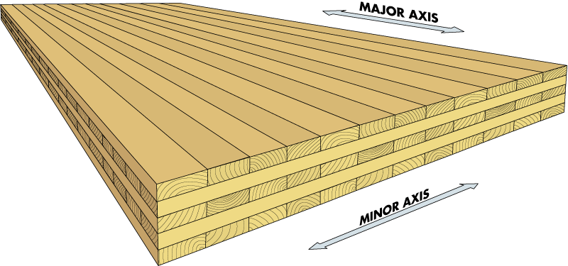
Figure 2. CLT panel.
The PRG 320 standard specifies that the laminations have a 5/8-inch minimum and 2-inch maximum thickness. Laminations used in North American CLT are frequently from 2×4 and 2×6 boards. The PRG 320 standard covers CLT panels up to 20 inches thick.
With CLT construction, panels are dimensionally stable in both the major and minor panel axis (Figure 2). Dimensional changes across the thickness of the panel are limited because of the use of dried lumber during manufacturing.
PRG 320 defines seven stress grades of CLT panels, which provide minimum strength requirements using visually-graded or machine-graded dimension lumber. CLT grades E1 through E4 use machine stress-rated lumber for layers parallel to the major axis. CLT grades V1 through V3 use visually-graded lumber for layers parallel to the major axis. All CLT grades defined in PRG 320 use visually-graded lumber for layers perpendicular to the major axis. Manufacturers can also supply additional CLT grades.
Structural Properties of CLT
For out-of-plane bending and shear behavior, and in-plane tension and compression behavior, the CLT layup creates a stronger and stiffer “major strength axis” and a weaker and softer “minor strength axis.” Subscripts 0 and 90 are used to differentiate properties in the major and minor directions, respectively.
Out-of-Plane Bending Strength
For out-of-plane flexural design, such as for gravity loads on a floor panel, the applied bending moment, Mb, must not be greater than the adjusted moment capacity and is written in the form:
Mb ≤ Fb (Seff)’
where the adjusted moment capacity, Fb(Seff)’, is calculated from the reference moment capacity, FbSeff, multiplied by adjustment factors presented in NDS Chapter 10. For allowable stress design (ASD), the load duration factor, CD, is applicable. Other adjustment factors including the wet service factor, CM, temperature factor, Ct, and beam stability factor, CL, are listed as potentially applicable to CLT panels in bending; however, they do not typically apply to CLT floor or roof panels within a building envelope.
The PRG 320 standard and manufacturers’ product reports provide the reference moment capacity, FbSeff, as an allowable design value. The major axis reference moment capacities in the CLT sections defined in PRG 320 range from 2,030 lb-ft/ft for the 3-ply V2 section to 18,375 lb-ft/ft for the 7-ply E1. Conversion of a reference moment capacity to a Load and Resistance Factor Design (LRFD) moment capacity can be performed using the KF, φ, and λ factors listed in NDS Chapter 10.
Provided the reference bending capacity in the major and minor strength axes, FbSeff,0 and FbSeff,90, the flexural strength design checks at ASD levels are simply:
Mb, 0 ≤ CD (∙) FbSeff,0
Mb,90 ≤ CD (∙) FbSeff,90
where (∙) provides for the atypical application of additional adjustment factors.
Out-of-Plane Shear Strength
Out-of-plane (interlaminar or rolling shear) capacities are based on testing according to the principles of APA PRG 320:
Vplanar ≤ Fs (Ib/Q)eff‘
where Vplanar is the applied shear demand and Fs(Ib/Q)eff‘ is the adjusted shear capacity which for ASD reduces to:
Fs(Ib/Q)eff‘ = (∙) Fs(Ib/Q)eff
Per NDS Chapter 10, the Load Duration Factor, CD, does not apply to this shear capacity check. Available CLT product reports use the term Vs for published values of the reference shear capacity, Fs(Ib/Q)eff, resulting in shear strength checks of:
Vplanar,0 ≤ (∙) Vs,0
Vplanar,90 ≤ (∙) Vs,90
Out-of-Plane Stiffness
PRG 320 and product reports provide calculated stiffness properties for flexural and shear deformation of CLT panels due to out-of-plane loads. The panel stiffness properties provided are EIeff,0 and EIeff,90 for flexure and GAeff,0 and GAeff,90 for shear deformations. These effective stiffness values take into account the varying direction and grades of laminations.
As shown in Figure 2, the major strength axis of the CLT panel is typically aligned with the long direction of the panel. In typical floor or roof applications, CLT panels primarily act as a one-way system where multiple panels are installed adjacent to each other, spanning between perpendicular supports. CLT panels can be used in multiple-span configurations. For such layouts, calculating floor or roof deflections under uniform loads can be performed by analyzing a strip (e.g., 1-foot width) of the CLT as a beam. Two-way spanning capabilities can be taken advantage of at corner overhangs and penetrations through panels. Using any structural analysis method with the capability to model the specific flexural and shear stiffness of the CLT, a designer can directly calculate internal forces and deflections as either a beam or two-way spanning floor system.
A simplified beam analysis method is presented in the 2015 NDS Section 10.4.1.1, where an apparent flexural stiffness, EIapp, combines the effective flexural and shear stiffness values. Commentary Section C10.4.1 provides an alternative formula of the apparent stiffness value, which can be used where effective bending and shear stiffness values are provided by the CLT manufacturer:
EIapp = [pmath]{EI_eff}/{1 + (K_s EI_eff)/(GA_eff L^2)} [/pmath]
The constant Ks depends on both the support conditions and applied loading pattern. For a single-span beam assuming pinned supports, Ks for uniformly distributed load equals 11.5 and Ks for a concentrated line load at mid-span equals 14.4. NDS Chapter 3 incorporates additional criteria regarding long-term deflection for CLT.
CLT Floor Design for Vibration
For many structural systems, designs of occupied floor systems are often governed by controlling floor vibrations for perceived occupant comfort and other serviceability concerns. CLT floor design is no different.
Prescriptive Span Limit
One method proposed by researchers at FPInnovations (Hu and Gagnon, 2012) to help select a CLT section that will have acceptable performance to occupants for walking excitations is presented in the CLT Handbook Chapter 7. This approach calculates an acceptable span limit based on the section properties and has been calibrated to subjective performance evaluations of bare CLT specimens. The recommended span limit can be written as:
l ≤ [pmath]1/12.05[/pmath] [pmath]{(EI_app)^0.293}/{(rho A)^0.122}[/pmath]
where l is the span, EIapp is the apparent stiffness of a 1-foot strip of a simply supported single span under uniform load, ρ is the specific gravity of the CLT, and A is the cross-sectional area of the 1-foot wide strip of CLT.
This approach also recommends keeping the fundamental frequency of CLT floors above 9 Hz. An estimate of the fundamental frequency of CLT as:
f = [pmath]2.188/{2l^2}[/pmath] [pmath]sqrt{EI_app/(rho A)}[/pmath]
As EIapp in the above two equations depends on span length, application of these criteria requires iterative calculations to determine recommended span length for a given CLT section. As a convenience to designers, North American manufacturers publish the recommended span limit for standard CLT sections based on this approach.
The CLT Handbook recommends using the same limit for CLT floors with multiple spans, suspended ceilings and light-weight floor toppings. An interim suggestion for addressing heavy-weight floor toppings (>20 lbs./sq. ft.) is also provided.
Alternative Vibration Criteria
With long spans or heavy floor loads, the period of vibration of floor systems can be difficult and uneconomical to keep above 9 Hz. Other established vibration criteria can be combined with an understanding of CLT floor behavior to design floors with acceptable vibration performance. One approach is the velocity control method included in the American Institute of Steel Construction Design Guide 11 (Murray et al., 2003) Chapter 6, which was used in the design of long-span CLT floors in the Timber Tower Research Project (SOM, 2013).
The velocity control method requires the selection of an acceptable velocity limit and loading condition. A two-dimensional analysis of the floor system can be performed to calculate the vibration response characteristics, including the period(s) of vibration. Alternative methods exist to estimate the floor flexibility including two-way spanning behavior, without performing a full two-dimensional plate analysis.
Advantages of general acceptance criteria, as in Design Guide 11 and standards such as ISO 10137, include being able to directly account for construction conditions that do not match the assumptions of the recommendations in the CLT Handbook and the ability to directly select more or less stringent design criteria as appropriate for the project under design. More accurate estimates of the floor stiffness and period through consideration of special boundary conditions, as in the Timber Tower Research Project, or by including the mass and stiffness contributions of topping slabs, as in Hamm et al. (2010), can explicitly consider floor configurations that are significantly outside the limitations of the recommended span-limit approach of the CLT Handbook.
Vibration-sensitive situations – e.g., the need to provide acceptable performance in response to rhythmic activities, or for sensitive equipment and occupancies – should receive much more rigorous evaluation than the methods outlined here.
CLT as Diaphragm
While the structural design of CLT is included in provisions of the 2015 NDS, lateral force transferring diaphragm systems of CLT are not included in the 2015 Special Design Provisions for Wind and Seismic (SDPWS). CLT diaphragm connection and system performance with various connection details and loading conditions is an area of ongoing research. CLT floor and roof systems are currently designed and built using CLT as a diaphragm material in accordance with principles of engineering mechanics and provisions of the NDS for connections and member design. Because of the size and strength of CLT panels, CLT diaphragm behavior is significantly influenced by the strength, flexibility, and ductility of the connections between CLT diaphragm panels and other force-resisting components. Some connection details are similar to nailed wood structural panel-sheathed diaphragms. Other panel-to-panel connection details use proprietary self-tapping screws and can result in connections stronger and stiffer than nailed connections.
Conclusions
While CLT is a relatively new building component to the U.S., product and design standards enable designers to design CLT floor and roof elements with confidence. The inclusion of CLT in the 2015 IBC and increasing North American manufacturing capabilities will likely lead to increased use of this innovative structural material. Also, organizations such as the Softwood Lumber Board, Binational Softwood Lumber Council, United States Department of Agriculture, Natural Resources Canada, and Canadian NEWBuildS Network are supporting considerable research to further support the use of CLT and other mass timber systems.▪
A similar article was published in the 2014 SEAOC Convention Proceedings. Content reprinted with permission.
References
ANSI/AWC NDS-2015 National Design Specification (NDS) for Wood Construction, American Wood Council, 2015.
ANSI/AWC SDPWS-2015 Special Design Provisions for Wind and Seismic (SDPWS), American Wood Council, 2015.
APA, 2012. ANSI/APA PRG 320-2012 Standard for Performance-Rated Cross-Laminated Timber, APA-The Engineered Wood Association, 2012.
Hamm, P., Richter, A., and Winter, S. “Floor Vibrations – New Results”, Proceedings of the World Conference on Timber Engineering, 2010.
Hu, L., and Gagnon, S., “Controlling Cross-Laminated Timber (CLT) Floor Vibrations: Fundamentals and Method”, Proceedings of the World Conference on Timber Engineering, July 2012, Auckland, NZ.
Karacabeyli, E. and Douglas B, editors. CLT Handbook: Cross-Laminated Timber. US Edition. FPInnovations, 2013; co-published by the United States Department of Agriculture Forest Service Forest Products Lab, Binational Softwood Lumber Council, APA – The Engineered Wood Association and WoodWorks-The Wood Products Council.
Murray, T., Allen, D, and Ungar, E, “Floor Vibrations Due to Human Activity,” Steel Design Guide Series 11, Second Printing, AISC, October 2003.
Popovksi, M., and Karacabeyli, E, “Seismic Behavior of Cross-Laminated Structures”, Proceedings of the World Conference on Timber Engineering, July 2012, Auckland, NZ.
SOM, 2013, Timber Tower Research Report, Final Report, Skidmore, Owings & Merrill, LLP, May 6th, 2013.